
Doping method of scheelite luminescent material

A luminescent material, scheelite technology, applied in the field of rare earth doping

Inactive Publication Date: 2010-08-18
陈连平
View PDF1 Cites 6 Cited by
  • Summary
  • Abstract
  • Description
  • Claims
  • Application Information

AI Technical Summary

Problems solved by technology

[0009] Therefore, how to overcome the drawbacks of the existing post-treatment doping technology that must undergo high-temperature treatment, and develop a rare earth doping technology at room temperature, so that AMO synthesized by electrochemical methods, precipitation methods, etc. 4 (A=Mg, Ca, Sr, Ba, Pb; M=W, Mo) achieve rare earth doping, which can make the synthesis process of tungsten (molybdenum)-based rare earth luminescent materials zero energy consumption, which will have important economic application value

Method used


Image

  • Doping method of scheelite luminescent material
  • Doping method of scheelite luminescent material

Examples


Embodiment 1

[0021] Example 1. Treatment time on CaWO 4 Polycrystalline film doped with Tb 3+ Effect of Concentration

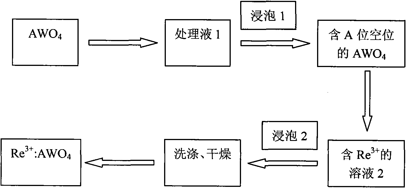
[0022] figure 1 The two-step processing shown (creation of A-site vacancies and rare-earth ion filling processing) can often be combined into one in actual operation. Treatment time and Tb in film 3+ There is the following relationship between the contents (as shown in Table 1). It can be seen from Table 1 that the doping concentration can also be effectively controlled by controlling the time of doping treatment.

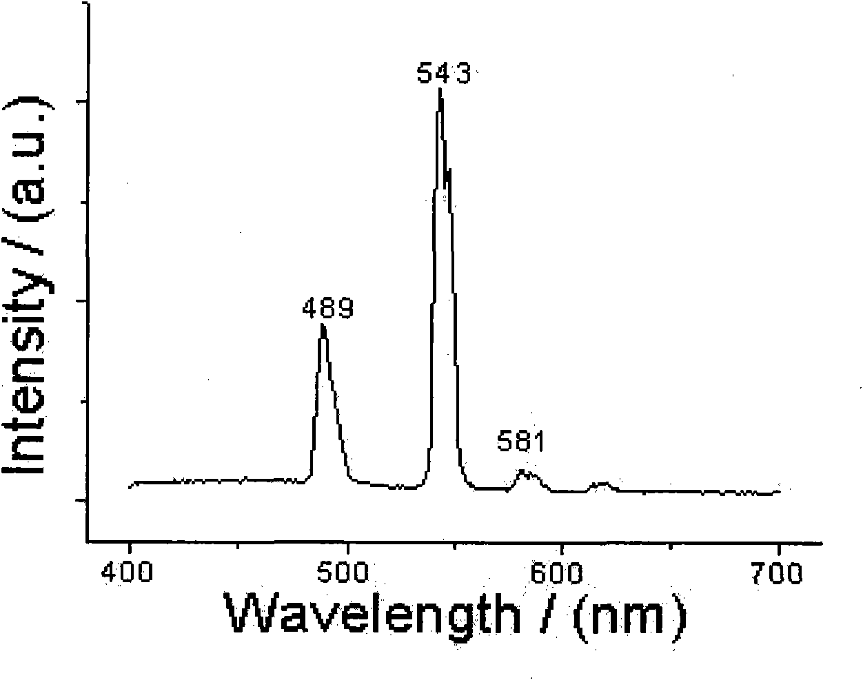
[0023] figure 2 CaWO 4 Polycrystalline film doped with Tb 3+ Photoluminescence spectra after 8 min of treatment. Under the excitation of 237nm light, CaWO 4 The broadband emission of the substrate near 450nm was suppressed, and a stronger green light was observed, namely Tb 3+ The luminescence of ions, and the half-maximum width of the line spectrum is less than 10nm. This shows that post-processing can achieve CaWO 4 Rare earth doping of polycrys...

Embodiment 2

[0026] Embodiment 2. Effect of Eu, Tb ratio on Eu, Tb content in film in the treatment solution

[0027] Table 2 shows the relationship between the content of Eu and Tb in the film and the ratio of Eu and Tb in the treatment solution. It can be seen from the table that by changing the ratio of Eu and Tb in the treatment solution, the doping concentration of Eu and Tb elements in the film can be controlled.

[0028] Table 2 The relationship between the content of Eu and Tb in the film and the ratio of Eu and Tb in the treatment solution

[0029] Eu / Tb in the treatment solution

Embodiment 3

[0030] Example 3. CaWO synthesized by precipitation method 4 Doped Tb content of powder

[0031] CaWO synthesized by precipitation method 4 Powders can also be doped using the doping methods introduced in this invention. Table 3 gives the Tb 3+ CaWO treated for 250 minutes in a solution with an ion concentration of 0.02 mol / l 4 Powder composition test results. According to the data in the table, it can be inferred that in CaWO 4 A luminescent shell layer with a high rare earth concentration is formed in the surface layer of the microcrystal, and the shell / core structure of the luminescent shell layer-matrix not only helps to improve the luminescent performance, but also saves the amount of rare earth.

[0032] Table 3Tb 3+ :CaWO 4 Comparison list of powder surface composition and body composition

[0033]


PUM


Abstract

The invention discloses a doping method of a scheelite luminescent material, belonging to the technical of material preparation. The doping method is characterized by comprising the steps of: manufacturing an A vacancy in a luminous matrix surface through the posttreatment, and recovering by rare-earth ions so as to synthesize a material with a luminous shell / nuclear structure, wherein the variety and the content of rare earths in Re<3+>:AMO4(A=Mg, Ca, Sr, Ba and Pb; M=W and Mo; Re=rare earth) can be controlled by changing the variety and the concentration and the treatment time of a treating liquid. The doping method is carried out under a room temperature environment without heat treatment; and the synthesized material has a rare earth luminous shell-matrix nuclear structure and excellent luminous property. Therefore, compared with the traditional doping method, the doping method has remarkable advantages of zero energy consumption, rare earth raw material saving, simple and convenient operation and the like.

Description

technical field [0001] The invention relates to a method for rare earth doping of tungstate and molybdate with scheelite structure, belongs to the technical field of material preparation, and is especially suitable for tungstate and molybdate synthesized by electrochemical method and precipitation method Rare earth doping of salt materials. Background technique [0002] Tungstates and molybdates with scheelite structure are an important class of optoelectronic functional materials, which have important applications in laser, display, detection and other fields. [0003] Compared with other synthesis methods, electrochemical technology can directly synthesize crystalline tungstate and molybdate materials in an aqueous solution at room temperature, which has outstanding advantages such as low energy consumption and suitable for industrial production. However, the tungstate and molybdate synthesized by this technology have single luminous properties, only intrinsic blue (green...

Claims


Application Information

Patent Timeline
Patent Type & Authority Applications(China)
IPC IPC(8): C09K11/68
Inventor 陈连平
Owner 陈连平
Learn More