Method for implementing airborne variable pressure hydraulic energy system

A technology of hydraulic energy and variable pressure, which is applied in the direction of fluid pressure actuation system components, fluid pressure actuation devices, mechanical equipment, etc. Problems such as large amount of heat generation and pollution generated by the system, to achieve the effects of reducing heat generation and pollutant generation, improving energy utilization rate, and improving adaptability

Inactive Publication Date: 2010-08-25
XIAN AIRCRAFT DESIGN INST OF AVIATION IND OF CHINA
View PDF4 Cites 7 Cited by
  • Summary
  • Abstract
  • Description
  • Claims
  • Application Information

AI Technical Summary

Problems solved by technology

[0002] At present, the airborne hydraulic system is developing towards high pressure and high power. While the pressure level of the hydraulic energy system is continuously increasing and the dynamic performance of the system is continuously optimized, because the traditional hydraulic energy system still adopts the design method of constant pressure and variable flow, so The reactive power of the system itself is also increasing. These reactive powers are not used by the hydraulic system, but are converted into heat and lost in vain. On the other hand, in order to effectively reduce the impact of heat generation on the hydraulic system, it is necessary to set Special heat dissipation devices, these heat dissipation devices need to use other media as heat sinks for heat exchange, and the current method of using fuel oil or ram air for heat dissipation has gradually reached the limit that can be tolerated, if other effective control measures are not taken, then It will inevitably increase the work risk of other systems on the machine; in addition, the hydraulic energy system will also produce a large amount of pollutant particles when it works for a long time. These pollutants are not only the performance of the internal wear of the hydraulic pump, but also when these pollutants enter the system , will also seriously affect the working life and reliability of other components
In order to effectively remove the influence of these factors on system performance, it is necessary to add corresponding system accessories to control temperature and pollution, which increases the system composition and increases the complexity of system design.
[0003] In short, the traditional constant pressure and variable flow hydraulic energy system has shortcomings such as low energy utilization efficiency, large amount of heat and pollution generated by the system itself, and complex system design, and needs to be improved to overcome the above problems

Method used


Image

  • Method for implementing airborne variable pressure hydraulic energy system
  • Method for implementing airborne variable pressure hydraulic energy system

Examples


Embodiment Construction

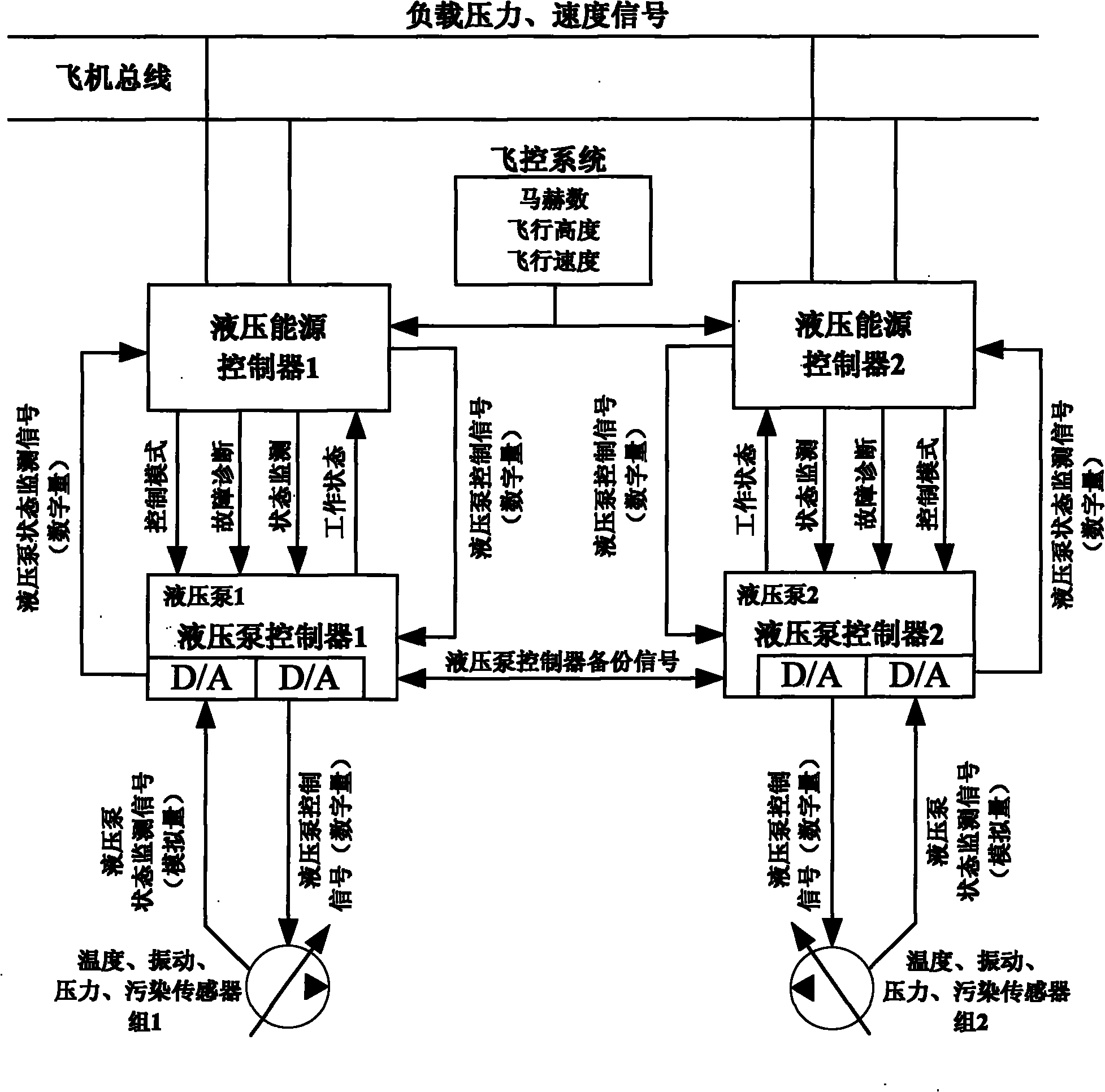
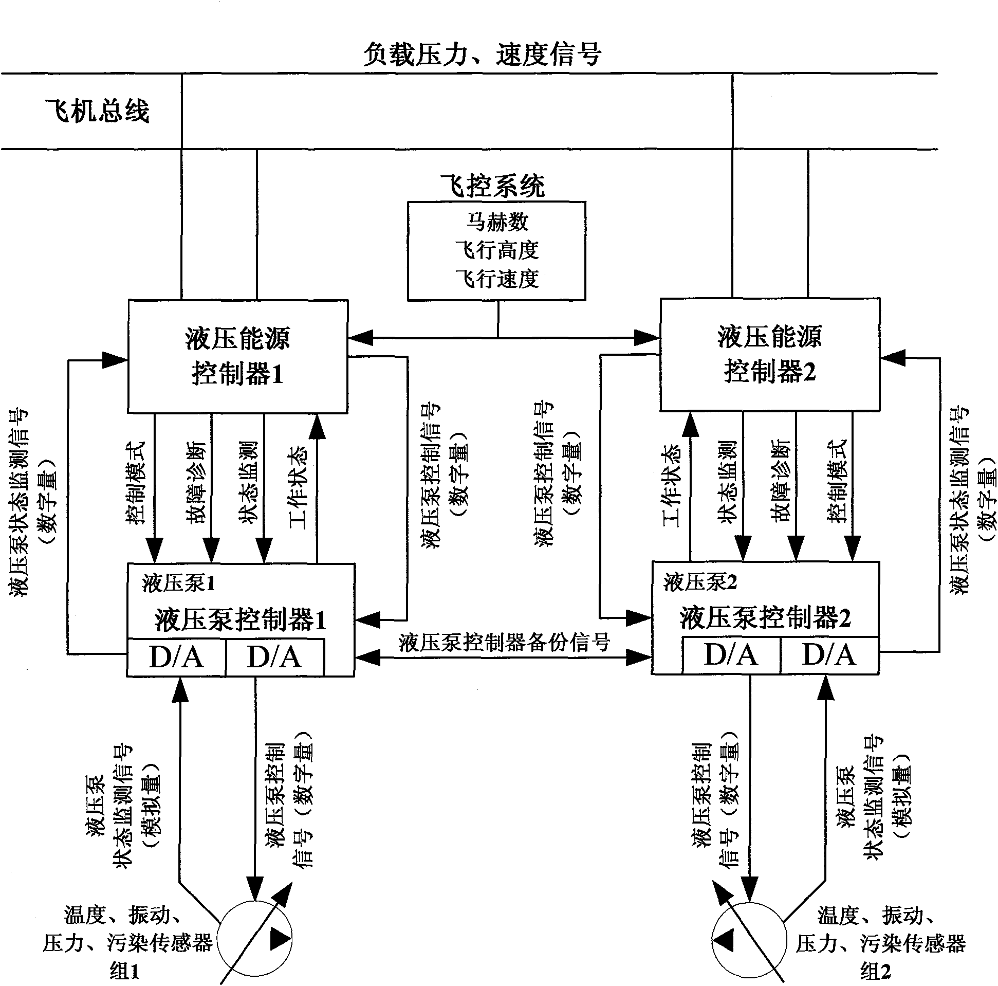
[0016] The present invention will be described in further detail below by means of the accompanying drawings.

[0017] Referring to Fig. 1, the variable pressure hydraulic energy system consists of three parts: hydraulic pump, hydraulic energy management control unit (including hydraulic energy controller and hydraulic pump controller) and vibration, temperature, pressure and pollution sensor groups, among which the hydraulic pump control The controller is integrated in the hydraulic pump.

[0018] The hydraulic pump is used as an actuator to generate hydraulic energy. The hydraulic energy management control unit issues working state instructions according to the flight state of the aircraft and the working state of the load to adjust the swash plate inclination angle of the hydraulic pump and the pressure regulating spring, so that the hydraulic pressure The pump can output hydraulic power (including output flow and output pressure) that meets the needs of the user's system. ...


PUM


Abstract

The invention discloses a method for implementing an airborne variable pressure hydraulic energy system. A hydraulic energy system is provided with a hydraulic pump, a hydraulic energy management control unit, and a vibration, temperature, pollution and pressure sensor group, wherein the management control unit consists of a hydraulic energy controller and a hydraulic pump controller; the hydraulic energy controller receives a plane bus signal and a flight state signal transmitted by a flight control system and sends a working state command to the hydraulic pump; the vibration, temperature, pollution and pressure sensor group senses the working state of the hydraulic pump and transmits monitored data to the hydraulic pump controller and performs fault diagnosis and fault isolation on the hydraulic pump; and the airborne variable pressure hydraulic energy system adopts a dual-pump parallel design mode. By using the method, the system can automatically regulate output flow and output pressure according to external load demand and can convert and work reliably in a plurality of working modes, thereby improving the energy utilization efficiency of a hydraulic system, reducing the thermal power loss of the system, and prolonging the service lives of the hydraulic system and accessories.

Description

technical field [0001] The invention belongs to the hydraulic energy system design technology and relates to the innovation of the design method of the variable pressure hydraulic energy system of an aircraft. Background technique [0002] At present, the airborne hydraulic system is developing towards high pressure and high power. While the pressure level of the hydraulic energy system is continuously increasing and the dynamic performance of the system is continuously optimized, because the traditional hydraulic energy system still adopts the design method of constant pressure and variable flow, so The reactive power of the system itself is also increasing. These reactive powers are not used by the hydraulic system, but are converted into heat and lost in vain. On the other hand, in order to effectively reduce the impact of heat generation on the hydraulic system, it is necessary to set Special heat dissipation devices, these heat dissipation devices need to use other medi...

Claims


Application Information

Patent Timeline
Patent Type & Authority Applications(China)
IPC IPC(8): F15B21/08
Inventor 李昆刘红秦成
Owner XIAN AIRCRAFT DESIGN INST OF AVIATION IND OF CHINA
Why Eureka
Try Eureka