Separated type heat-pipe plate solar collector and special working refrigerant thereof

The technology of a solar panel and a split heat pipe is applied in the field of solar energy utilization, which can solve the problems of high cost, difficult to popularize, and cannot be used, and achieves the effects of simple structure, easy popularization and application, and wide application range.

Inactive Publication Date: 2010-08-25
四川锦尚博美科技有限公司
View PDF0 Cites 7 Cited by
  • Summary
  • Abstract
  • Description
  • Claims
  • Application Information

AI Technical Summary

Problems solved by technology

[0004] The technical problem to be solved by the present invention is to make major technical improvements to the existing heat collectors that cannot be used in winter, or have high cost, and are not easy to popularize. A split heat pipe solar panel heat collector is proposed, which has high efficiency, Low cost, can still be used normally in winter

Method used


Image

  • Separated type heat-pipe plate solar collector and special working refrigerant thereof
  • Separated type heat-pipe plate solar collector and special working refrigerant thereof

Examples


Embodiment 1

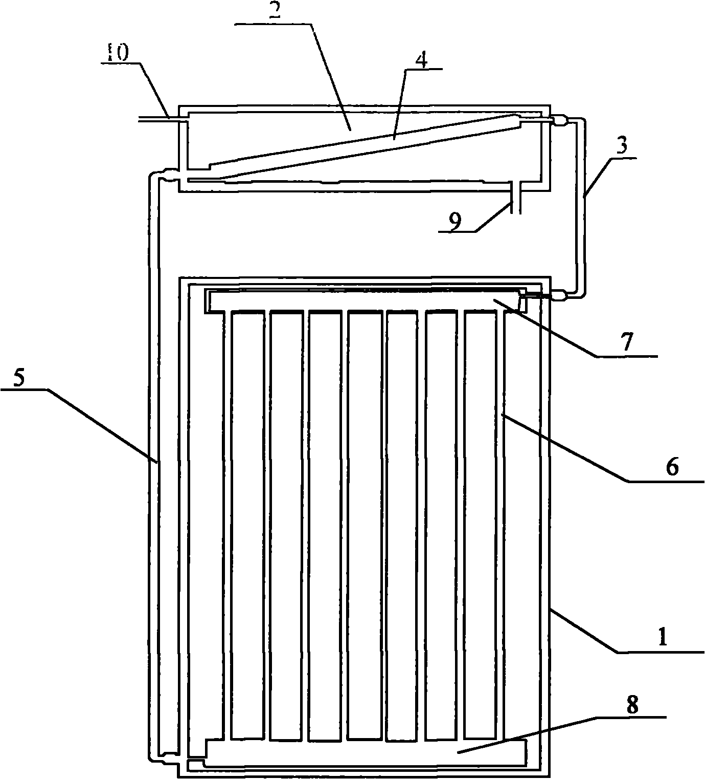
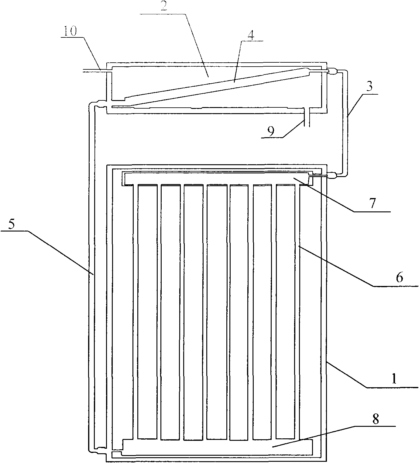
[0025] As shown in Figure 1, the split-type heat pipe solar panel collector consists of a collector frame 1, a working fluid circulation loop and a heat storage bin 2, and the collector frame 1 and heat storage bin 2 pass through the working fluid circulation loop connect them.

[0026] The working fluid circulation circuit is formed by sequentially connecting the heat pipe evaporator, the steam rising pipe 3, the condensing pipe 4, and the liquid descending pipe 5. Hot water outlet pipe 10. The lower end of the condensing pipe 4 communicates with the liquid downcomer 5 , and the higher end communicates with the steam upcomer 3 .

[0027] The heat pipe evaporator is composed of an evaporator vertical pipe 6 , a steam cavity 7 located above the evaporator vertical pipe 6 and communicating with it, and a liquid collection chamber 8 located below the evaporator vertical pipe 6 and communicating therewith. And the steam chamber 7 communicates with the steam ascending pipe 3 , an...

Embodiment 2

[0032] The utility model relates to a working fluid specially used in a split-type heat pipe solar panel heat collector, and the working fluid is a multiphase composite working fluid.

[0033] The multi-phase-change composite working fluid is one or more of liquid-gas phase-change substances or solid-liquid phase-change substances.

[0034] The liquid-gas phase change substance is one or more of water, ammonia, pentane, acetone, methanol, ethanol, and heptane.

[0035] The solid-liquid phase change substance is one or more of inorganic water and salts, fatty acids, alkali metals, high-temperature molten salts, higher aliphatic hydrocarbons, alcohol polyhydrocarbyls, and compound salts.


PUM


Abstract

The invention discloses a separated type heat-pipe plate solar collector and a special working refrigerant thereof. The separated type heat-pipe plate solar collector comprises a solar collector frame, a working refrigerant circulation loop and a heat storage bin, wherein the solar collector frame is connected with the heat storage bin by the working refrigerant circulation loop. The working refrigerant circulation loop is formed by sequentially connecting a heat-pipe evaporator, a vapor uptake, a condenser pipe, a liquid downtake, wherein the heat-pipe evaporator comprises an evaporator stand pipe, a vapor chamber and a liquid collecting chamber, the vapor chamber is positioned above the evaporator stand pipe and is communicated with the evaporator stand pipe, and the liquid collecting chamber is positioned under the evaporator stand pipe and is communicated with the evaporator stand pipe. The working refrigerant which is specially used for the separated type heat-pipe plate solar collector is a polyphase composite working refrigerant which is one or more than one of liquid-gas phase matters or solid-liquid phase matters. The separated type heat-pipe plate solar collector has simple structure, is easy to popularize and apply, can be normally used in winter, can be widely used for a solar heating system and is especially suitable for a solar building integration hearing system.

Description

technical field [0001] The present invention relates to the field of solar energy utilization, in particular to a split type heat pipe solar panel solar collector, which increases the types of existing solar panel collectors and can heat liquids (such as water, oil), gases (such as air), and solids (such as metal heating), expanding the category of heating substances. [0002] The invention also relates to a working medium specially used in the split heat pipe solar panel heat collector, which can heat the substance to the required temperature through repeated phase change cycles. Background technique [0003] Solar energy is recognized as a sustainable and environmentally friendly energy source. With the continuous development of science and technology, people's use of solar energy has gradually developed from passive and semi-active to active development and utilization. How to effectively use solar energy to make up for the shortage of limited energy sources such as coal...

Claims


Application Information

Patent Timeline
Patent Type & Authority Applications(China)
IPC IPC(8): F24J2/32F24J2/30F24J2/46F24S10/30F24S10/95
CPCY02E10/44
Inventor 宋剑
Owner 四川锦尚博美科技有限公司
Why Eureka
Try Eureka