Method for improving recovery rate of thick massive viscous oil reservoir by controlling burning gas injection speed

A heavy oil reservoir and recovery technology, which is applied in the direction of production fluid, earthwork drilling, wellbore/well components, etc., can solve problems such as low economic benefits, flameout, failure, etc., achieve safe and effective fire operation, and improve fire performance. The effect of sweeping volume and optimized design

Active Publication Date: 2010-09-01
PETROCHINA CO LTD
View PDF10 Cites 23 Cited by
  • Summary
  • Abstract
  • Description
  • Claims
  • Application Information

AI Technical Summary

Problems solved by technology

As the thickness of the oil layer increases, the cross-sectional area of ​​fire in the vertical direction of the fire line also increases correspondingly. Excessive gas injection speed often leads to low economic benefits, while too low gas injection speed can lead to flameout and failure.

Method used


Image

  • Method for improving recovery rate of thick massive viscous oil reservoir by controlling burning gas injection speed
  • Method for improving recovery rate of thick massive viscous oil reservoir by controlling burning gas injection speed
  • Method for improving recovery rate of thick massive viscous oil reservoir by controlling burning gas injection speed

Examples


Embodiment 1

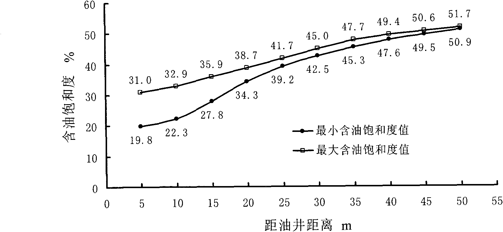
[0095] Oilfield 1 is a monocline oil reservoir bounded by faults on three sides. It has the typical characteristics of deep burial, simple structure, extremely thick oil layers, and no internal barriers and interlayers. The buried depth of the oil layer is 1460-1600m, the thickness of the oil layer is 145m, the remaining oil saturation is 0.45, the porosity is 21.6%, the permeability is 860md, and the viscosity of degassed crude oil under formation conditions is 4500mPa.s; in the early stage, the development was mainly based on throughput, and the current formation pressure is low , only 2-3MPa, large underground water storage, only 30% water recovery rate, the highest remaining oil saturation between wells is 61%.

[0096] (1) Carry out rough screening according to the geological characteristics and development status of the oilfield. The reservoir meets the following conditions: oil layer thickness > 30m, single layer thickness greater than 10m accounts for 70% of the total...

Embodiment 2

[0103] Oilfield 2 is a monocline oil reservoir bounded by faults on three sides. It has the typical characteristics of deep burial, simple structure, extremely thick oil layers, and no internal barriers and interlayers. The buried depth of the oil layer is 1460-1600m, the thickness of the oil layer is 76.5m, the remaining oil saturation is 0.43, the porosity is 24.2%, the permeability is 1530md, and the viscosity of degassed crude oil under formation conditions is 2320mPa.s; Low, only 1 ~ 2MPa, large underground water storage, water recovery rate is only 28%, the highest remaining oil saturation between wells is 59.3%.

[0104] (1) Carry out rough screening according to the geological characteristics and development status of the oilfield. The reservoir meets the following conditions: oil layer thickness > 30m, single layer thickness greater than 10m accounts for 70% of the total thickness, remaining oil saturation > 0.45, porosity > 0.18, permeability > 200md, degassed crude...


PUM


Abstract

The invention relates to a method for improving recovery rate of a thick massive viscous oil reservoir by controlling burning gas injection speed, which mainly comprises the following steps of: determining the thickness and residual oil saturation of an oil layer at the burning front edge by stages according to the condition and rule of fire-flooding live wire wave by combining fine research results of double analogs in a massive oil reservoir chamber; then determining planar residual oil saturation and residual oil at different positions apart from a gas injection well, and predicting the burned section area of the burning front edge, the non-homogeneity of the reservoir and the optimal configuration relationship between the residual oil and the gas injection speed; and finally, dynamically adjusting the single-well gas injection speed by stages, and selecting a variable and lower burning gas injection speed to maintain stable and normal burning on the premise of ensuring combustion. The method can fulfill the purposes of improving the burning wave and volume of the massive oil reservoir, the development effect of the burning oil layer and the final recovery rate.

Description

technical field [0001] The invention relates to an enhanced oil recovery technology for heavy oil reservoirs, which is applicable to a method for increasing oil recovery by fire flooding in massive thick oil reservoirs, and specifically relates to a method for increasing oil recovery in thick massive heavy oil reservoirs. A method to enhance reservoir recovery by controlling combustion gas injection rate in reservoir huff and puff. Background technique [0002] In-situ combustion, also known as underground combustion or intra-layer combustion, also known as fire-flooding, is a thermal oil recovery technology that generates heat inside the oil layer. Oil recovery by burning oil layer is to artificially create an environment in the reservoir that can oxidize and burn crude oil by using coke-like substances deposited on the mineral matrix during the pyrolysis reaction as fuel and oxygen injected into the air as a combustion aid under formation conditions. Under the condition o...

Claims


Application Information

Patent Timeline
Patent Type & Authority Applications(China)
IPC IPC(8): E21B43/243
Inventor 龚姚进任芳祥孙洪军胡士清曹光胜高飞户昶昊韩冰
Owner PETROCHINA CO LTD
Why Eureka
Try Eureka