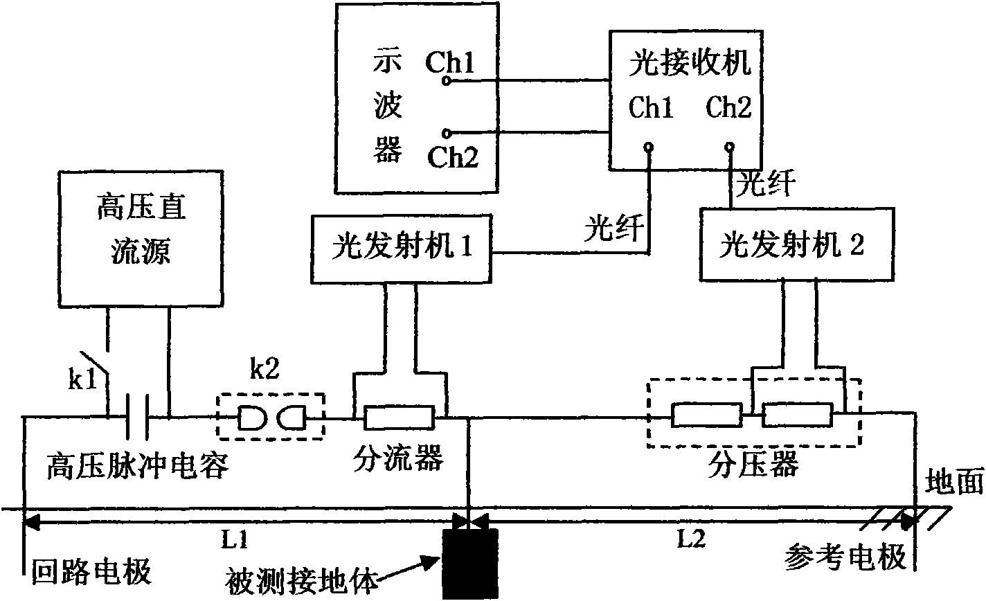
Impact grounding impedance measuring system and measuring method thereof

A technology of impact ground impedance and measurement system, which is applied in the direction of ground resistance measurement, measurement of electrical variables, and measurement devices, can solve the problems of not reflecting the impact characteristics and impedance characteristics well, large measurement errors, and test waveform interference, etc., to achieve The effects of reducing measurement errors, eliminating interference, and accurate measurement values

Inactive Publication Date: 2010-09-01
PLA UNIV OF SCI & TECH
View PDF5 Cites 33 Cited by
  • Summary
  • Abstract
  • Description
  • Claims
  • Application Information

AI Technical Summary

Problems solved by technology

[0004] In short, the existing impact grounding impedance measurement system can not reflect the impact characteristics and impedance characteristics of the grou

Method used


Image

  • Impact grounding impedance measuring system and measuring method thereof
  • Impact grounding impedance measuring system and measuring method thereof
  • Impact grounding impedance measuring system and measuring method thereof

Examples


Embodiment 1

[0036] Such as figure 1As shown, the impact grounding impedance measurement system of the present invention includes a high-voltage DC source, a high-voltage pulse capacitor, a discharge circuit, a high-voltage charging switch, a moving ball gap switch, a resistor shunt connected in series with the high-voltage pulse capacitor and the discharge circuit, and a A water resistor divider connected to the reference ground electrode, a high-voltage pulse source console, a digital oscilloscope, and a two-way optical fiber signal transmission system. The optical fiber signal transmission system includes optical transmitters No. 1 and No. 2, optical fibers, optical fibers No. 1 and No. 2 The receiver, the voltage divider and the shunt are all connected with the digital oscilloscope Ch1 and Ch2 through the optical fiber signal transmission system. High-voltage DC sources include autotransformers, dry-type step-up transformers, high-voltage silicon stacks, charging ammeters, and current-...

Embodiment 2

[0050] Using the measurement system and measurement method in Example 1 to carry out the actual measurement of the impact grounding impedance of a single round steel grounding body, the impulse voltage waveform 5 (a) and the impulse current waveform 5 (b) are obtained, and Figure 5 (b) is obtained by calculation. c) Impulse ground impedance time domain waveform.


PUM


Abstract

The invention provides an impact grounding impedance measuring system which comprises a high-voltage direct current source, a high-voltage pulse capacitor, a discharging loop, a high-voltage charging switch, a high-voltage discharging switch, a resistance current divider, a water resistance voltage divider, a high-voltage pulse source control table, a digital oscilloscope and an optical fiber signal transmitting system, wherein the resistance current divider is connected with the high-voltage pulse capacitor and the discharging loop in series; the water resistance voltage divider is connected with a reference grounding electrode of the discharging loop; the optical fiber signal transmitting system comprises an optical transmitter, an optical fiber and an optical receiver; the voltage divider and the current divider are respectively connected with the digital oscilloscope through the optical fiber signal transmitting system; and the high-voltage discharging switch is a motion ball gap switch. The invention has the advantages of compact structure, small volume, convenient carrying, simple operation, accurate and stable measuring value, reduction of electromagnetic interference and reduction of measuring error.

Description

technical field [0001] The invention relates to a grounding impedance measuring system and its measuring method, in particular to an impact grounding impedance measuring system and its measuring method. Background technique [0002] Impulse grounding resistance (Transient grounding resistance, TGR) reflects the impact characteristics of the grounding device under the action of lightning current. At the beginning of the last century, people widely used equipment such as voltage and ammeter to conduct voltammetry grounding resistance experiments, and the experimental errors were extremely large. Beginning in the 1950s, the E-type shaker of the former Soviet Union replaced the voltammetry, and the power source was a hand generator. The production of grounding resistance meters in my country began in the 1970s. ZC series (such as ZC-28, ZC-29, etc.) are better than E-type shakers in terms of structure, measurement range, accuracy and division value. However, due to the reason ...

Claims


Application Information

Patent Timeline
IPC IPC(8): G01R27/20G01R27/08
Inventor 高成吴海石立华李炎新陈彬周璧华刘晓
Owner PLA UNIV OF SCI & TECH
Why Eureka
Try Eureka