
Oxygen-rich combustor

An oxygen-enriched combustion and burner technology, applied in the direction of burners, combustion types, combustion methods, etc., can solve problems such as environmental pollution and nitrogen oxide emissions, and achieve the effect of good technology

Active Publication Date: 2010-09-08
HUAZHONG UNIV OF SCI & TECH
View PDF3 Cites 38 Cited by
  • Summary
  • Abstract
  • Description
  • Claims
  • Application Information

AI Technical Summary

Problems solved by technology

[0002] In the current boiler pulverized coal combustion power generation technology, there are high emissions of carbon dioxide and nitrogen oxides, which cause great pollution to the environment

Method used


Image

  • Oxygen-rich combustor
  • Oxygen-rich combustor
  • Oxygen-rich combustor

Examples


example 1

[0033] A schematic diagram of a tangentially movable swirl generator for the burner of the present invention is as follows Figure 6 As shown, the connection mode, working process and function of this swirler in the external secondary wind swirl generator are described below: the regulating box 19 is installed on one end of the external secondary air cavity body 10, and the transmission rod 20 is connected to the regulating box 19 connected, the other end is connected to the circular gear 21 and the semi-circular gear 24 connected to the rotating gland 23, the lower end of the rotating gland 23 is connected to the mover 26 evenly distributed on the coaxial circumference, and the stator 25 connected to the lower end is paired Teething, the upper end of the rotary gland 23 is coaxially connected with the fixed gland 22. The operation mode of the hydrocyclone is to rotate the valve of the adjustment box 19, the transmission rod 20 rotates the connected mover 26, and cooperates wi...

example 2

[0035] A schematic diagram of an axially movable swirl generator for the burner of the present invention is as follows: Figure 7 As shown, the connection mode, working process and function of this cyclone in the external secondary wind swirl generator are described below: the regulating box 19 is installed on one end of the external secondary air cavity body 10, and the transmission rod 20 is connected to the regulating box. 19 connected, the other end is connected with the blade 28, the blade 28 is evenly installed between the inner and outer ring pipes 27, and the two ring pipes 27 play the role of fixing the blade 28, the bottom of the blade is fixed on the outer surface of the inner ring pipe, The tops are all fixed to the inner surface of the outer ring pipe. The operation mode of the swirler is to turn the valve of the adjustment box 19, the transmission rod 20 is raised or lowered, the blades 28 and the connecting parts will rise or fall together, and part of the airfl...


PUM


Abstract

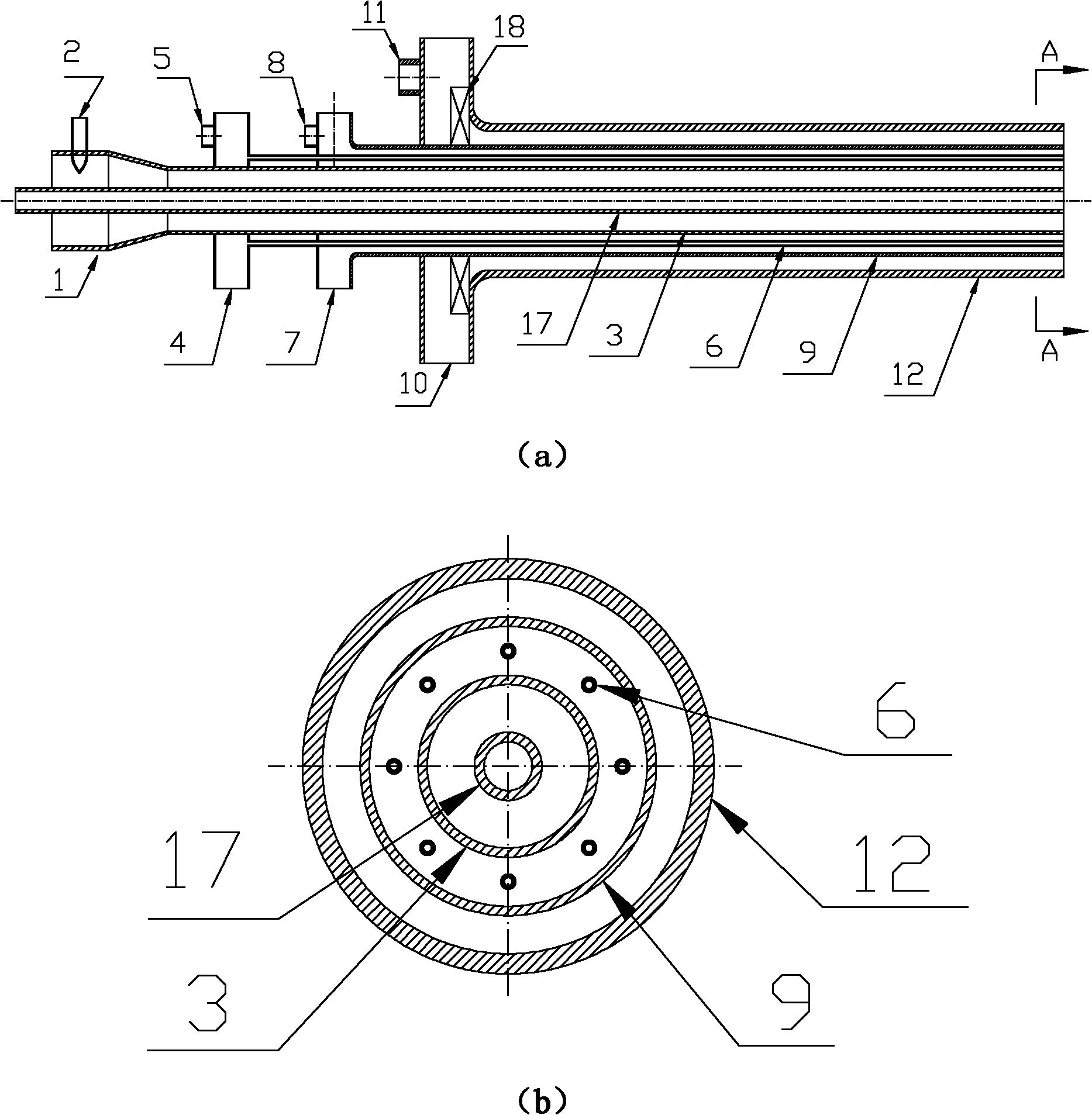
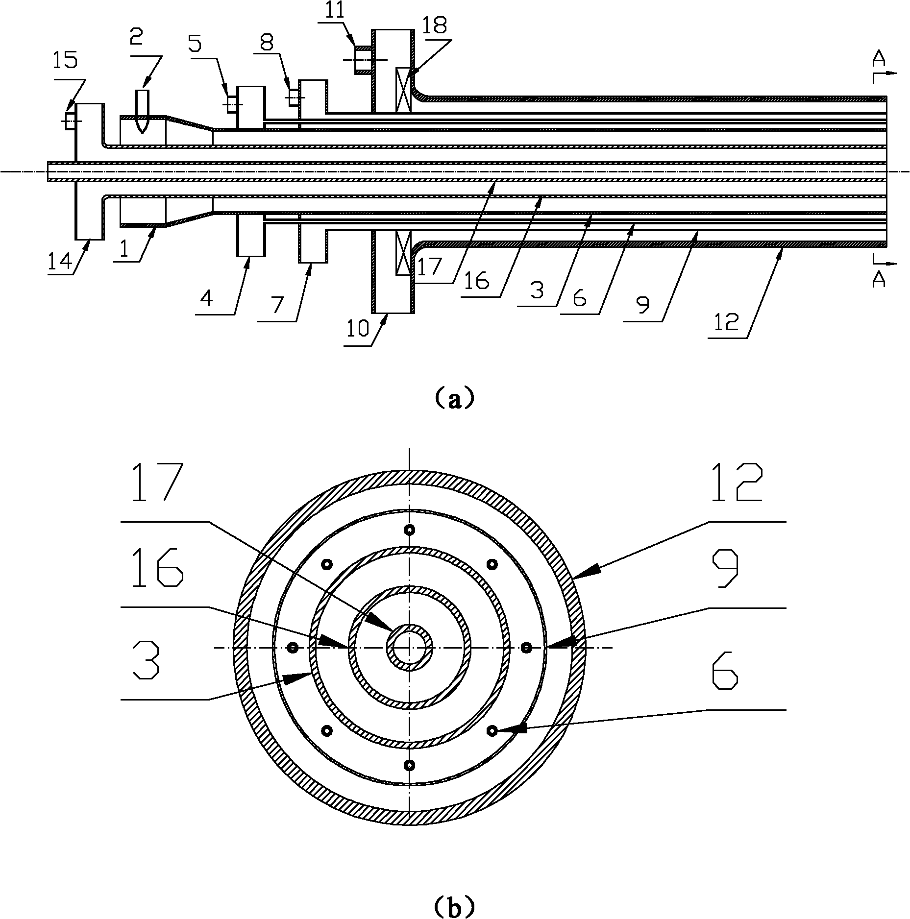
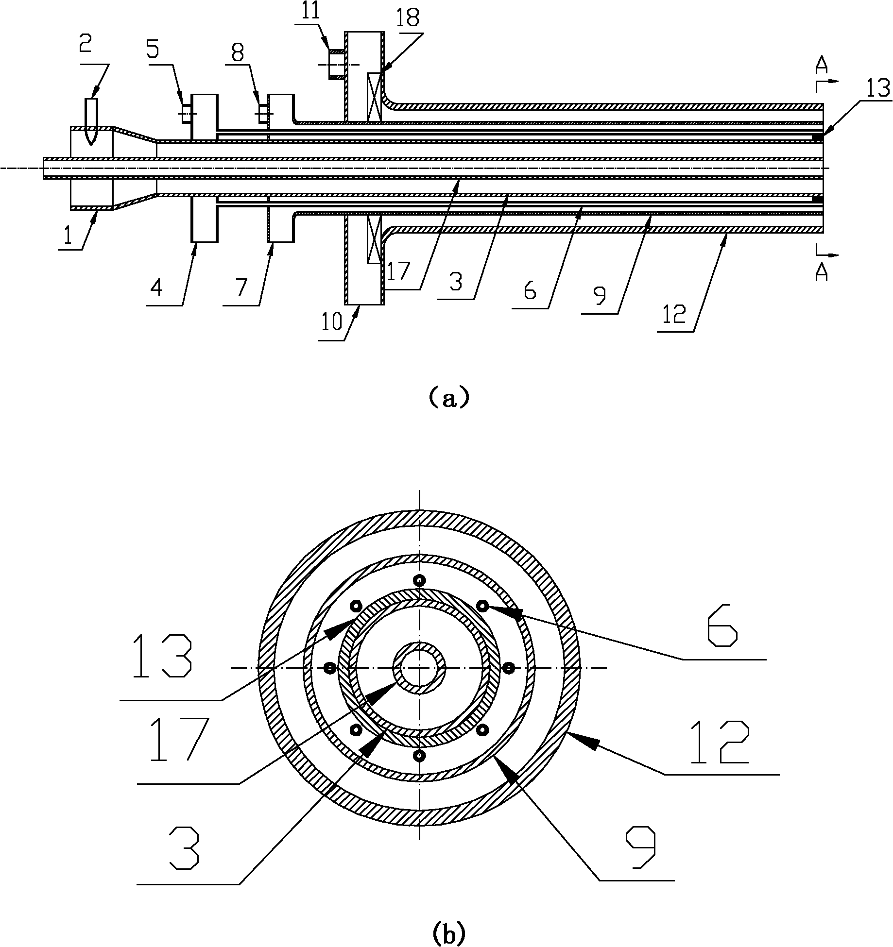
The invention discloses an oxygen-rich combustor, which comprises an oil gun barrel, a primary air swirl generator, an inner secondary air generator and an outer secondary air swirl generator arranged coaxially, wherein an oxygen injector is positioned between the primary air swirl generator and the inner secondary air generator and comprises an oxygen chamber, an oxygen inlet pipe and oxygen pipes, the oxygen inlet pipe is positioned at one end of the oxygen chamber, and the oxygen pipes are connected with the other end of the oxygen chamber; and the oxygen pipes are uniformly distributed along the circumference around the axial direction. The air or a circulating flue gas is used as primary air for conveying coal powder; the oxygen injector conveys the air or pure oxygen; the inner secondary air and the outer secondary air mainly are the air or the pure oxygen / the circulating flue gas; the swirling number adjustability of the outer secondary air swirl generator, the action of high-speed oxygen jet flows and the oxygen mixed mode ensure that primary and secondary wind momentums are adjustable, and are favorable for sufficient combustion, low pollutant emission and heat and mass transfer.

Description

technical field [0001] The invention relates to a burner, in particular to an oxygen-enriched burner used in boilers and industrial kilns for pulverized coal combustion. Background technique [0002] In the current boiler pulverized coal combustion power generation technology, there are high emissions of carbon dioxide and nitrogen oxides, which cause great pollution to the environment. CO emissions from coal-fired power plant boilers 2 my country's CO 2 More than 70% of emissions developed with CO 2 New coal-fired power generation technology with capture is the key to achieving large-scale reductions in CO emissions 2 the fundamental way. Among various emission reduction technologies, oxy-combustion technology replaces combustion-supporting air with high-purity oxygen, and at the same time uses flue gas circulation to adjust the medium flow rate and heat transfer characteristics in the furnace, which can obtain high volume concentration of CO-rich 2 smoke. For coal-fi...

Claims


Application Information

Patent Timeline
IPC IPC(8): F23D1/02F23L7/00
CPCY02E20/322Y02E20/32Y02E20/34
Inventor 柳朝晖刘敬樟郑楚光陈胜王林张泰黄晓宏彭科孔红兵
Owner HUAZHONG UNIV OF SCI & TECH
Learn More