Energy-saving gas stove

A gas stove and gas technology, applied in the field of gas stoves, can solve the problems of heat consumption, high temperature, waste gas overflow, etc., and achieve the effects of improving combustion efficiency, thermal efficiency, and thermal efficiency.

Active Publication Date: 2010-09-08
GUANGDONG DEHE TECH CO LTD
5 Cites 11 Cited by

AI-Extracted Technical Summary

Problems solved by technology

The air preheater of the above-mentioned device needs to obtain heat from the burner, so it needs to consume a certain amount of heat energy; at the same time, because the device cannot discharge the exhaust gas such as carbon monoxide and carbon dioxide generated during the combustion of gas in time, the exhaust gas gradually accumulates in the isolation cover. Affects the air supply required for full combustion of the ga...

Method used

Due to the low density of the hot exhaust gas generated by combustion, the hot exhaust gas tends to accumulate above the gas combustion chamber 9, so the upper part of the side wall of the isolation cover 8 is provided with an exhaust hole 81, and one end of the exhaust gas discharge pipe 4 communicates with the The exhaust hole 81 on the upper part of the side wall of the isolation cover 8 is conducive to the timely and complete discharge of the exhaust gas, thereby effectively avoiding the negative impact of the exhaust gas on the full combustion of the gas.
Referring to Figure 3 and Figure 4 at the same time, the heat exchange device 6 includes a helical air duct 5 and a helical exhaust gas discharge pipe 4 inside it, between the air duct 5 and the exhaust gas discharge pipe 4 They are separated by a common partition wall 45, and the partition wall 45 is relatively thin. The arrangement of the heat exchange device 6 simplifies the production process and reduces the difficulty of production. In addition, the partition wall 45 is made of a heat conducting plate, and the side wall 46 , the upper cover plate 47 and the lower bottom plate 48 are all made of a heat insulating plate. In the heat exchange device 6, the hot exhaust gas flows in from the first air inlet 41 of the exhaust gas discharge pipe 4, and flows through the first air outlet 42, and then the heat-exchanged exhaust gas is discharged outdoors; The air inlet 51 flows in, and flows through the second air outlet 52 , and then reaches the pre-mixing chamber 31 . The dotted lines with arrows in FIG. 2 indicate the direction of gas flow outside the heat exchange device 6 . The air flow in the above-mentioned air duct 5 and exhaust gas discharge pipe 4 circulates in reverse in the heat exchange device 6 . The above arrangement ensures sufficient heat exchange between the high-temperature hot exhaust gas and the cold air flowing in from the outside, so that the cold air is effectively preheated in the heat exchange device 6, thereby effectively improving the thermal efficiency of the gas stove. In addition, the cross-sectional shape of the air duct 5 and the exhaust gas discharge pipe 4 can be set according to actual needs, but when the cross-section is rectangular, the cold air can achieve an ideal preheating effect. Of course, the air duct 5 and the exhaust gas discharge pipe 4 in the heat exchange device 6 can also perform heat exchange in the manner shown in FIG. 5 . As shown in FIG. Wall 54 separates it. Cold air enters from the third air inlet 511 of the air duct 5, and flows out from the third air outlet 512; hot exhaust gas enters from the fourth air inlet 411 of the exhaust gas discharge pipe 4, and flows out from the fourth air outlet 412, through The configuration of this structure can also achieve a good heat exchange effect.
Referring to Figures 1 and 2, an energy-saving gas stove includes a gas st...

Abstract

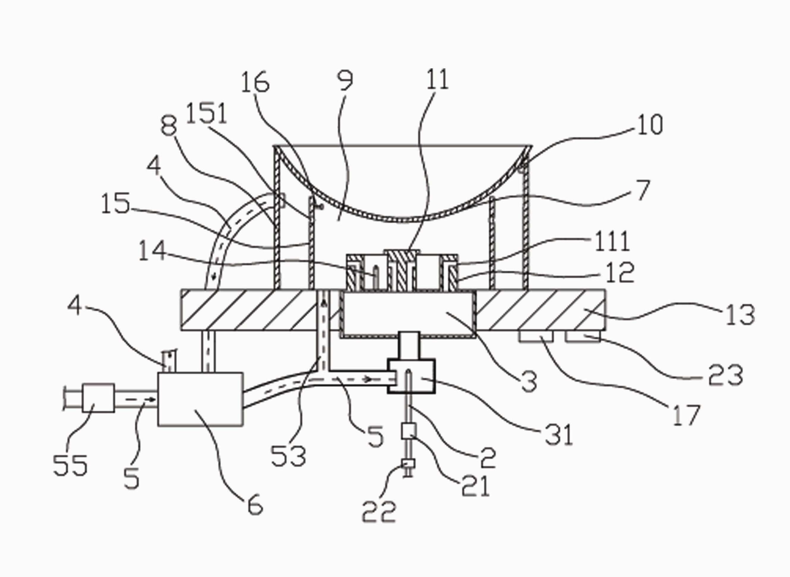
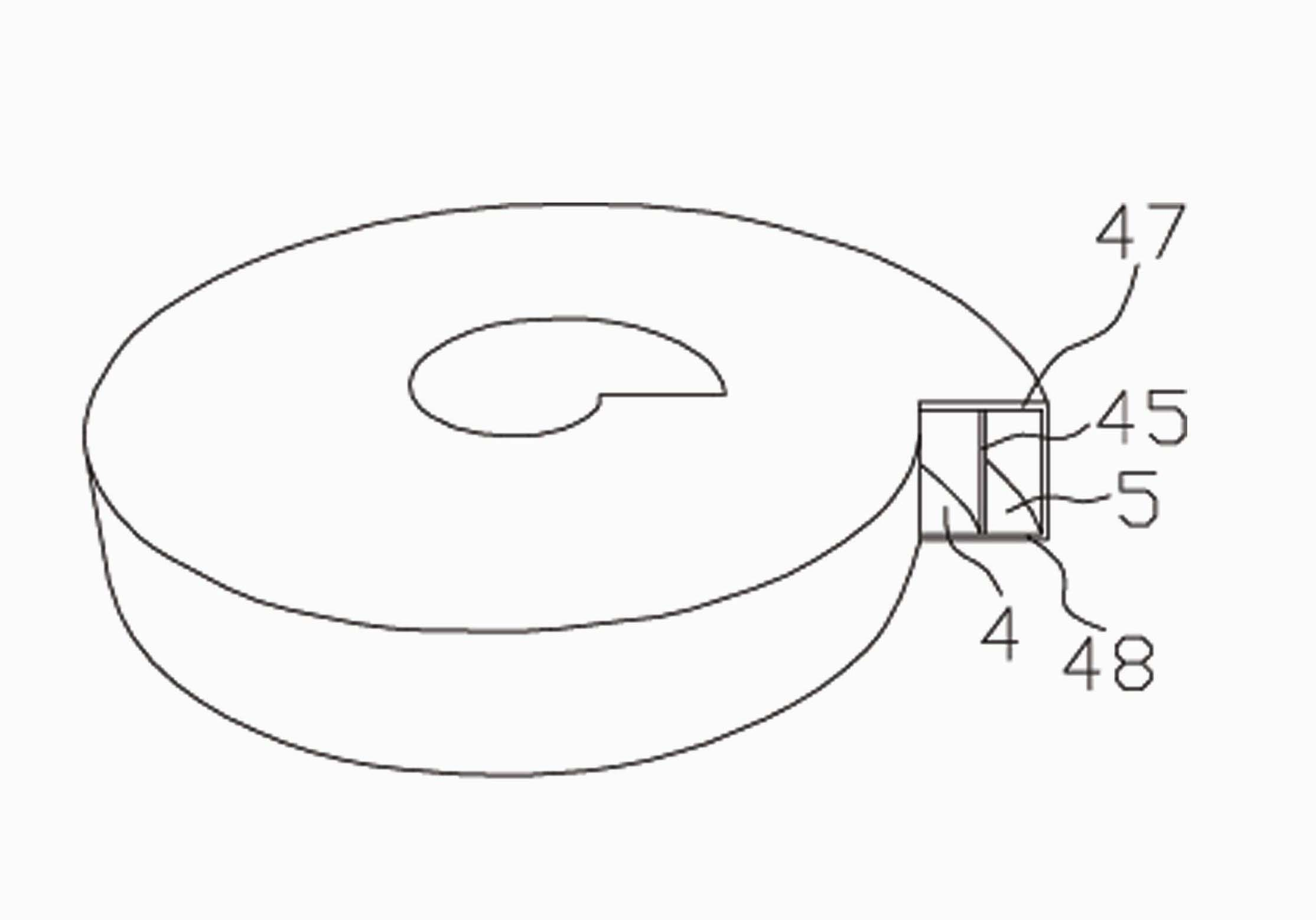
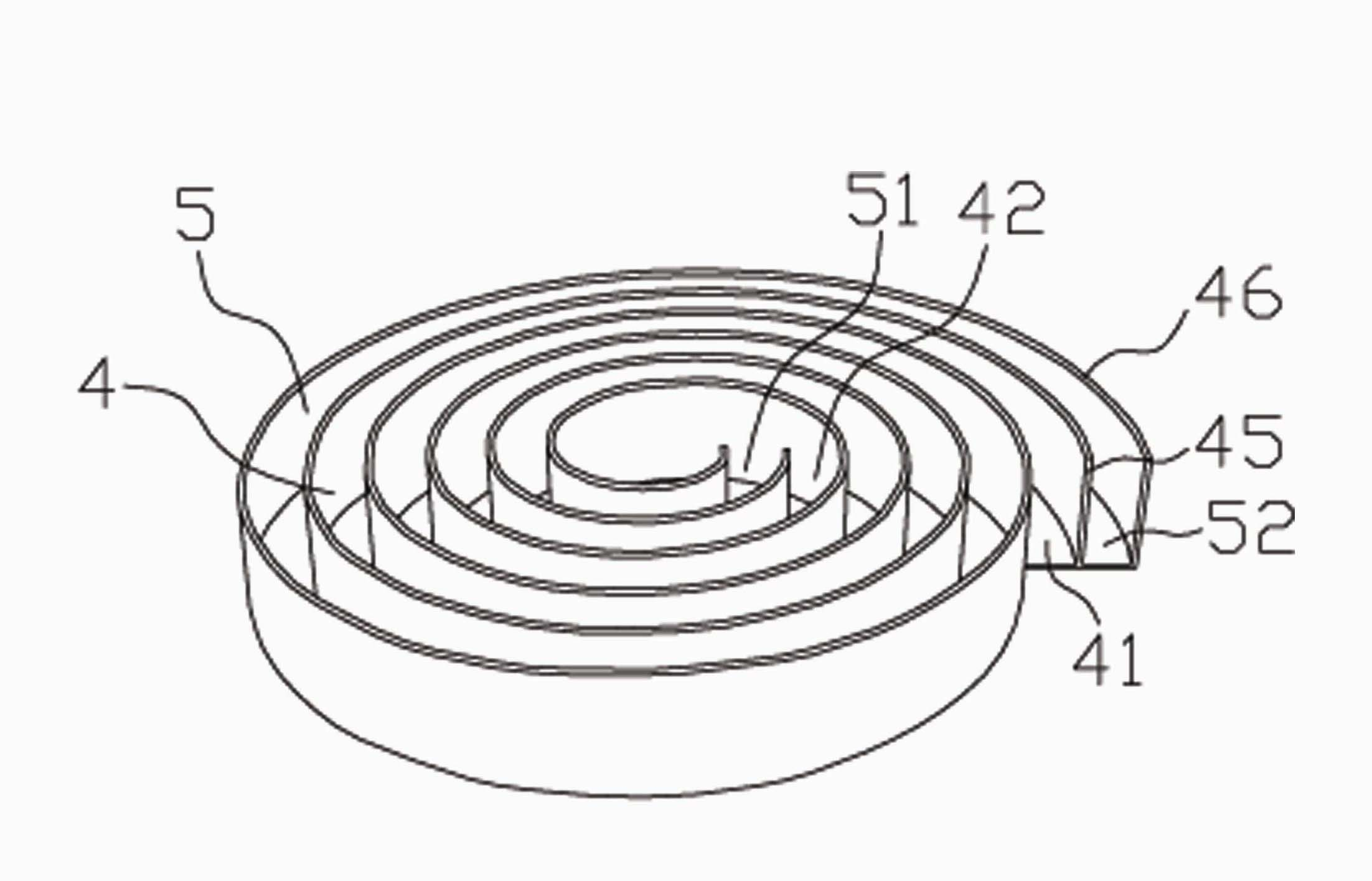
The invention discloses an energy-saving gas stove, which comprises a gas stove body, a combustor, a gas guide pipe and a gas mixing chamber, wherein the gas guide pipe is communicated with the gas mixing chamber and the combustor is communicated with the upper part of the gas mixing chamber. The gas stove additionally comprises an isolation hood, a waste gas exhaust pipe, an air guide pipe and a heat exchange device, wherein the isolation hood isolates combustion hot gas from the outside and the heat exchange device is used for heat exchange between incoming cold air and exhausted hot waste gas. The invention has the advantages that not only the gas is combusted more fully but also the thermal efficiency is effectively improved because heat contained in the waste gas produced during combustion is used for preheating the cold air participating in combustion, and the impact on body health caused by the waste gas is effectively avoided because the waste gas is fully exhausted. Moreover, since the heat generated by the gas in the closed gas combustion chamber is not rapidly dissipated around, the thermal efficiency of the gas stove is promoted.

Application Domain

Technology Topic

Image

  • Energy-saving gas stove
  • Energy-saving gas stove
  • Energy-saving gas stove

Examples

  • Experimental program(3)

Example Embodiment

Example one
1 and 2, an energy-saving gas stove includes a gas stove body 13, an igniter 14, a burner 1, a gas duct 2, and a gas mixing chamber 3 arranged on the gas stove body 13, and the igniter 14 is arranged at At the gas outlet of the combustor 1, the gas conduit 2 communicates with the gas mixing chamber 3, and the combustor 1 is connected to the upper part of the gas mixing chamber 3. It includes a cylindrical burner 11 and a cylindrical burner 11 The annular combustor 12 of the combustor 11 is provided with gas holes 111 on the side walls of the combustor 1. The gas stove also includes an exhaust gas discharge pipe 4, an air duct 5, cold air for inflow and hot exhaust gas discharged A heat exchange device 6 for heat exchange and an isolation cover 8 that separates the hot combustion gas from the outside. The isolation cover 8 is provided between the bottom of the pot 7 and the gas stove body 13, and one end of the exhaust gas exhaust pipe 4 is connected to the isolation The other end of the cover 8 is connected to the outside through the heat exchange device 6, one end of the air duct 5 is connected to the gas mixing chamber 3 through the premixing chamber 31, and the other end is connected to the outside through the heat exchange device 6 The cold air is connected. The hot exhaust gas flows out through the exhaust gas discharge pipe 4 through the heat exchange device 6, and the cold air flows in through the air duct 5 through the heat exchange device 6. Therefore, the cold air and hot exhaust gas circulate in the heat exchange device 6 in reverse, so that the cold air can be better. Ground preheating effect.
The isolation cover 8 is an annular wall whose bottom surface abuts against the gas stove body 13. In order to make the upper end surface of the isolation cover 8 and the pot bottom 7 have a good sealing effect, the upper surface of the isolation cover 8 The end surface is an annular inclined surface that is sealed to the bottom of the pot 7. When in use, the pot bottom 7 is sealed and placed on the upper end surface of the isolation cover 8. The bottom of the isolation cover 8 is sealed against the upper surface of the gas stove body 13. The inner wall of the isolation cover 8 and the pot bottom 7, the outer side wall of the burner 1 and the gas stove body 13 jointly form a closed gas combustion chamber 9, and the gas can be fully burned in the gas combustion chamber 9. At the same time, in order to reduce the heat loss in the gas combustion chamber 9, it is often necessary to provide a heat insulation reflection layer on the inner wall of the isolation cover 8. In addition, a pressure sensor 10 is provided on the top of the isolation cover 8. The gas stove also includes an on-off control valve 22 provided on the gas pipe 2 and a control for receiving signals from the pressure sensor 10 and controlling the operation of the on-off control valve 22. The controller 23 is installed on the gas stove body 13. When the bottom of the pot 7 is in contact with the isolation cover 8, the bottom of the pot 7 will press the pressure sensor 10. At this time, the switch control valve 22 is opened and the gas pipe 2 is ventilated; when there is no contact, the pressure sensor 10 will not feel the pressure. At this time, the controller 23 controls the switch control valve 22 to close, and the gas pipe 2 is not ventilated, so as to realize the purpose of automatically shutting off the gas when the gas stove has no pot. Of course, the pressure sensor 10 can also be replaced by a proximity switch or other sensing devices that can feel the pressure of the pan. In addition, in order to fully combust the gas, the air duct 5 is also provided with a branch pipe 53 which communicates with the gas combustion chamber 9. Part of the air is mixed with the gas and the other part of the air directly enters the gas combustion chamber 9.
The gas stove further includes a fire barrier 15 which is an annular wall provided between the burner 1 and the isolation cover 8, and a plurality of vents are provided on the fire barrier 15 151. The size and shape of the vent 151 is not limited and can be adjusted at will according to actual needs. The setting of the fire barrier 15 can reduce the outward impact of the flame. In addition, the height of the fire insulation layer 15 is smaller than the height of the insulation cover 8.
Due to the low density of the hot exhaust gas produced by combustion, the hot exhaust gas tends to accumulate above the gas combustion chamber 9. Therefore, the upper part of the side wall of the isolation cover 8 is provided with an exhaust hole 81, and one end of the exhaust gas discharge pipe 4 is connected to the The exhaust hole 81 on the upper part of the side wall of the isolation cover 8 will help the exhaust gas to be discharged in time and completely, thereby effectively avoiding the negative influence of the exhaust gas on the full combustion of the gas.
In addition, the gas stove also includes a temperature sensor 16 for the temperature of the combustion hot gas, a flow control valve 21 provided on the gas pipe 2, and a controller 17 for receiving signals from the temperature sensor 16 and controlling the operation of the flow control valve 21. . The temperature sensor 16 is installed on the inner side wall of the fire barrier 15. The controller 17 is installed on the gas stove body 13. The temperature sensor 16 transmits the temperature change signal of the combustion hot gas to the controller 17, and the controller 17 controls the flow control valve 21 according to the above signal to increase or decrease the amount of gas in the gas pipe 2 so that the combustion hot gas maintains a certain temperature . The above arrangement can ensure that the food in the pot will not overheat, thereby effectively reducing the generation of harmful substances.
The top of the gas mixing chamber 3 communicates with the combustor 1, and the bottom surface of the gas mixing chamber 3 communicates with a premixing chamber 31 provided at the lower end of the gas mixing chamber 3 through a gas guide hole. The gas duct 2 and the air duct 5 are both connected to the premixing chamber 31. The gas in the gas duct 2 and the air in the air duct 5 are initially mixed in the premixing chamber 31, and then fully mixed in the gas mixing chamber 3. , The fully mixed gas mixture is finally fully burned on the burner 1.
3 and 4 at the same time, the heat exchange device 6 includes a spiral-shaped air duct 5 and a spiral-shaped exhaust gas discharge pipe 4 arranged inside, between the air duct 5 and the exhaust gas discharge pipe 4 They are separated by a common partition wall 45, and the partition wall 45 is relatively thin. The arrangement of the heat exchange device 6 simplifies the production process and reduces the production difficulty. In addition, the partition wall 45 is made of a heat conducting plate, and the side walls 46, the upper cover plate 47 and the lower bottom plate 48 are all made of heat insulating plates. In the heat exchange device 6, the hot exhaust gas flows in from the first air inlet 41 of the exhaust gas discharge pipe 4, and flows through the first air outlet 42, and then the heat exchanged exhaust gas is discharged outdoors; the air flows from the second air duct 5 The air inlet 51 flows in, flows through the second air outlet 52, and then reaches the premixing chamber 31. The dotted line with arrows in FIG. 2 indicates the direction of gas flow outside the heat exchange device 6. The air flow in the air duct 5 and the exhaust gas discharge pipe 4 circulates in the reverse direction in the heat exchange device 6. Through the above arrangement, the heat energy of the hot exhaust gas with high temperature and the cold air flowing in from the outside are fully exchanged, so that the cold air is effectively preheated in the heat exchange device 6, thereby effectively improving the thermal efficiency of the gas stove. In addition, the cross-sectional shape of the air duct 5 and the exhaust gas discharge pipe 4 can be set according to actual needs, but when the cross-section is rectangular, the cold air can achieve an ideal preheating effect. Of course, the air duct 5 and the exhaust gas discharge pipe 4 in the heat exchange device 6 can also be used for heat exchange as shown in FIG. 5. As shown in FIG. 5, the air duct 5 and the exhaust gas exhaust pipe 4 pass through a common The wall 54 separates. Cold air enters from the third air inlet 511 of the air duct 5 and flows out from the third air outlet 512; hot exhaust gas enters from the fourth air inlet 411 of the exhaust gas exhaust pipe 4 and flows out from the fourth air outlet 412, passing through The arrangement of this structure can also achieve a good heat exchange effect.
In addition, in order to make the air flow in from the air duct 5 more conveniently, a blower 55 can usually be connected to the air duct 5.

Example Embodiment

Example two
6 and 7, the structure of this embodiment is basically the same as that of the first embodiment above. The main difference is that the gas stove of this embodiment also includes a high-temperature resistant fire shield 18, which is roughly inverted Goblet shape. The flame shield 18 is sleeved on the combustor 1, and a funnel-shaped hot gas outlet 181 is formed above the combustor 1. The funnel-shaped hot gas outlet 181 facilitates the diffusion of hot gas. The flame shield 18 has a certain blocking effect on the flame, which can avoid the problem of uneven heating of the bottom 7 caused by the direct contact of the flame with the bottom 7 of the pot. At the same time, the heat formed by the combustion of the gas on the burner 1 is flushed from the hot gas outlet. And heat the bottom 7 of the pot.
Referring to FIG. 7, the gas stove further includes a bimetal 19 for sensing the hot gas of combustion and a flow control valve 191 controlled by the bimetal 19. The flow control valve 191 is installed on the gas pipe 2, and one end of the bimetal 19 is installed at the hot gas outlet 181 of the flame shield 18 to accurately measure the temperature change of the hot gas. The bimetal 19 can react according to the temperature of the hot combustion gas detected by the flow control valve 191, and effectively adjust the amount of gas flowing into the gas pipe 2 so as to keep the hot combustion gas at a certain temperature. The above arrangement can ensure that the food in the pot is not overheated, thereby effectively avoiding the generation of harmful substances.
In addition, the fire insulation layer 15 and the isolation cover 8 are connected by an annular partition 20, which is provided on the top of the fire insulation layer 15 and the isolation cover 8, and the partition 20 It is hermetically connected with the fire barrier 15 and the isolation cover 8. A pressure sensor 10 is installed at the abutment between the partition plate 20 and the bottom 7 of the pot. The gas stove further includes an on-off control valve 22 arranged on the gas pipe 2 and for receiving signals from the pressure sensor 10 and controlling the switch. The controller 23 for the operation of the valve 22 is installed on the gas stove body 13. When the bottom of the pot 7 is in contact with the partition 20, the bottom of the pot 7 will press the pressure sensor 10. At this time, the switch control valve 22 is opened, and the gas pipe 2 is ventilated; when there is no contact, the pressure sensor 10 cannot feel the pressure. At this time, the controller 23 controls the switch control valve 22 to close, and the gas pipe 2 is not ventilated, so as to realize the purpose of automatically shutting off the gas when the gas stove has no pot.

Example Embodiment

Example three
Referring to Figure 8, the structure of this embodiment is basically the same as that of the above-mentioned second embodiment. The main difference is that the partition 20 of this embodiment is provided with a plurality of vent holes 152 at intervals, and the pot bottom 7 is in contact with the top of the isolation cover 8. , There is a gap between the fire barrier 15 and the bottom of the pot 7. In this way, the combustion hot gas can be filled in the entire isolation cover 8, thereby increasing the heating area of ​​the bottom of the pot 7, thereby improving the thermal efficiency. In addition, the exhaust gas generated by combustion can also flow into the exhaust gas discharge pipe 4 from the vent 152, which is more conducive to the discharge of the exhaust gas.

PUM

no PUM

Description & Claims & Application Information

We can also present the details of the Description, Claims and Application information to help users get a comprehensive understanding of the technical details of the patent, such as background art, summary of invention, brief description of drawings, description of embodiments, and other original content. On the other hand, users can also determine the specific scope of protection of the technology through the list of claims; as well as understand the changes in the life cycle of the technology with the presentation of the patent timeline. Login to view more.

Similar technology patents

Spray nozzle and gas turbine with same

ActiveCN104566471AImprove fire stabilityImprove combustion efficiencyContinuous combustion chamberPartially premixed combustionPower equipment
Owner:CHINA UNITED GAS TURBINE TECH CO LTD

Gas roller way kiln

Owner:青岛铸英特陶科技有限公司

Classification and recommendation of technical efficacy words

  • Improve combustion efficiency
  • Improve efficiency

Gas burner capable of adjusting gas to be self-recycling

Owner:GUANGZHOU INST OF ENERGY CONVERSION - CHINESE ACAD OF SCI

Biomass solid formed fuel anti-slagging additive and preparation method thereof

Owner:ACADEMY OF PLANNING & DESIGNING OF THE MINIST OF AGRI
Why Eureka
Try Eureka