
Blazed fiber bragg grating demodulation-based micro-displacement sensor and detection method

A blazed fiber grating and micro-displacement sensor technology, which is applied in light demodulation, optics, instruments, etc., can solve the problems that strain signal and temperature signal cannot be separated and detected, fiber grating sensor is cross-sensitive, and the system stability is not high. Achieve the effect of solving the problem of cross-sensitivity, low cost, and simple instrument structure

Inactive Publication Date: 2010-09-08
NORTHEASTERN UNIV
View PDF3 Cites 17 Cited by
  • Summary
  • Abstract
  • Description
  • Claims
  • Application Information

AI Technical Summary

Problems solved by technology

Because there are moving parts in the detection process of this method, piezoelectric ceramics have a hysteresis phenomenon, so the stability of the system is not high, and the cost of this method is relatively high, generally more than 100,000 yuan
[0003] In addition, due to the cross-sensitivity of strain and temperature of fiber grating itself, the sensor design and signal demodulation method based on fiber grating either cannot realize the separate detection of strain signal and temperature signal, or need to add special structures and components , combined with a special algorithm to achieve the separate detection of strain and temperature, in order to solve the problem of cross-sensitivity of fiber grating sensors

Method used


Image

  • Blazed fiber bragg grating demodulation-based micro-displacement sensor and detection method
  • Blazed fiber bragg grating demodulation-based micro-displacement sensor and detection method
  • Blazed fiber bragg grating demodulation-based micro-displacement sensor and detection method

Examples


Embodiment Construction

[0017] The specific structure, principle and measurement process of the present invention will be further described below in conjunction with the accompanying drawings.

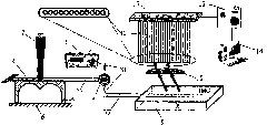
[0018] figure 1 A schematic diagram of the overall principle structure of the micro-displacement sensor based on blazed fiber grating demodulation provided by the present invention. The light emitted by the broadband light source is sent to the fiber grating for sensing through the fiber circulator, and the fiber grating is pasted between one end of the double arched beam and the center point. The measured micro-displacement is provided by the helical micrometer screw. When a micro-displacement is applied to the upper surface of the double arched beam, the beam will be deformed, so that the fiber grating pasted on it will be subjected to strain. The reflection spectrum signal of the fiber grating for sensing is modulated by micro-displacement and then reflected, and then sent to the blazed fiber grating for...


PUM

PropertyMeasurementUnit
Center wavelengthaaaaaaaaaa
Thicknessaaaaaaaaaa
Lengthaaaaaaaaaa

Abstract

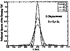
The invention relates to a blazed fiber bragg gating demodulation-based micro-displacement sensor and a detection method and belongs to the technical field of photoelectric detection. The sensor consists of a wideband light source 1, an optical circulator 2, optical fiber links (31, 32, 33), fiber bragg gating 4 used for sensing, a double-arched beam 5, a base 6, a helix millesimal screw 7, a blazed fiber bragg gating 8 used for demodulation, a refractive index matching liquid groove 9, a columnar lens 10, an optical fiber array 11, a CCD photoelectricity prober 12, a signal processing unit 13 and a computer 14. The sensor is characterized in that a reflective spectrum signal of the fiber bragg gating 4 used for sensing is broadened under the action of the detected micro-displacement; the signal is sent to the optical fiber array 11 by the blazed fiber bragg gating 8 used for demodulation with a certain beam angle and is transmitted to the CCD photoelectricity prober 12; the error of the measurement caused by light intensity wave, optical fiber transmission loss and the like is avoided on the basis of a gauss fitting algorithm and by identifying the detected displacement corresponding to the facula size received by the CCD photoelectricity prober 12.

Description

technical field [0001] The invention relates to a micro-displacement sensor and a detection method based on blazed fiber grating demodulation, and belongs to the technical field of photoelectric detection. Background technique [0002] At present, the existing optical fiber grating displacement detection systems mostly use piezoelectric ceramic displacement drivers to deform piezoelectric ceramics under the action of electrical signals, so that the reflection wavelength signal of the fiber grating sensor pasted on it moves. The amount of wavelength shift enables the measurement of displacement. Or use some smart structures to convert the displacement into the strain of the fiber grating, and generally the fiber grating is subjected to equal strain, so that the reflection wavelength of the fiber grating sensor moves. However, most of the technologies and methods for detecting the shifting amount of the reflected wavelength of the fiber grating sensor are large and complex, a...

Claims


Application Information

Patent Timeline
IPC IPC(8): G01B11/02G01D3/028G02F2/00
Inventor 赵勇
Owner NORTHEASTERN UNIV
Learn More