High temperature vacuum brazing clamp for internally finned tube

A high-temperature vacuum, inner fin technology, applied in manufacturing tools, welding equipment, auxiliary devices, etc., can solve the problem that stainless steel tube flatness, inner fin roundness, fin peak flatness cannot be accurately guaranteed, and welding effect cannot be obtained, etc. problems, to achieve the effect of reducing manufacturing costs, improving strength and plasticity, and reducing contact thermal resistance

Inactive Publication Date: 2010-09-15
XI AN JIAOTONG UNIV
View PDF7 Cites 5 Cited by
  • Summary
  • Abstract
  • Description
  • Claims
  • Application Information

AI Technical Summary

Problems solved by technology

For the inner finned tube with very irregular welding surface, due to the limitation of the manufacturing process, the flatness of the inner surface of the stainless steel tube, the roundness of the inner fin and the flatness of the fin peak cannot be accurately guaranteed
The inventors have shown through preliminary experiments that even if a core tube with the same outer diameter as the inner diameter of the inner fin is inserted into the inner finned tube and then subjected to high-temperature vacuum brazing, a good welding effect cannot be obtained

Method used


Image

  • High temperature vacuum brazing clamp for internally finned tube
  • High temperature vacuum brazing clamp for internally finned tube
  • High temperature vacuum brazing clamp for internally finned tube

Examples


Embodiment Construction

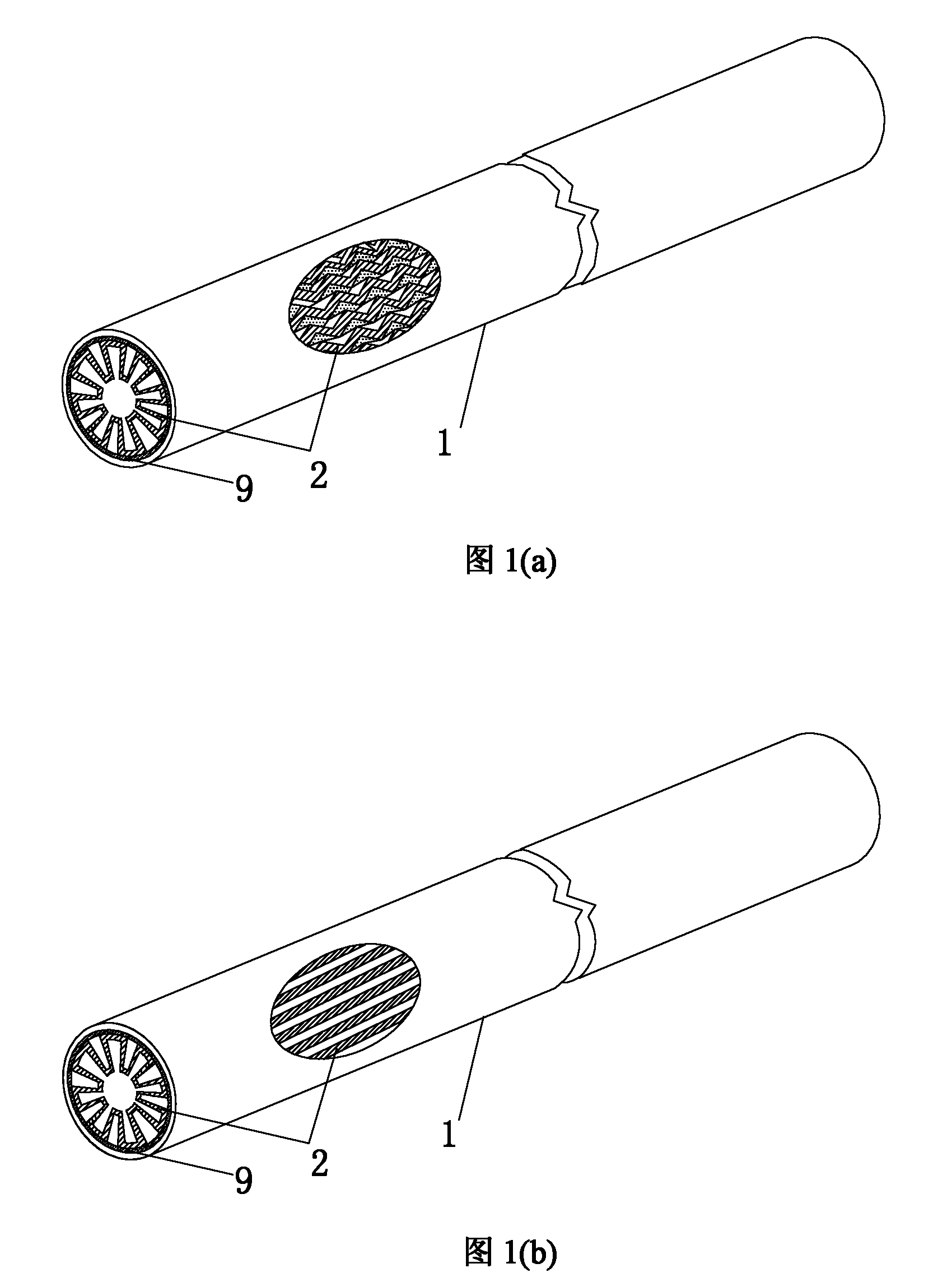
[0029] figure 1 (a) and figure 1 (b) has described two kinds of inner fin tube structure schematic diagrams that the present invention needs brazing, wherein, figure 1 (a) The inner fin 2 described is a longitudinal corrugated fin, figure 1 The inner fins 2 described in (b) are longitudinal straight fins. In order to obtain a good heat transfer effect, the fin peaks on the outer surface of the inner fin 2 must be welded to the inner surface of the outer tube 1 to reduce the contact thermal resistance, but it can be seen from Figure (1) that there are many and irregular welding points, The nickel-based solder 9 used in high-temperature vacuum brazing is a foil strip with a thickness of 0.03-0.05mm, which puts forward very high requirements on the assembly process of the inner finned tube before brazing. This patent is aimed at this The problem proposes a new mold for high temperature vacuum brazing of inner finned tubes.

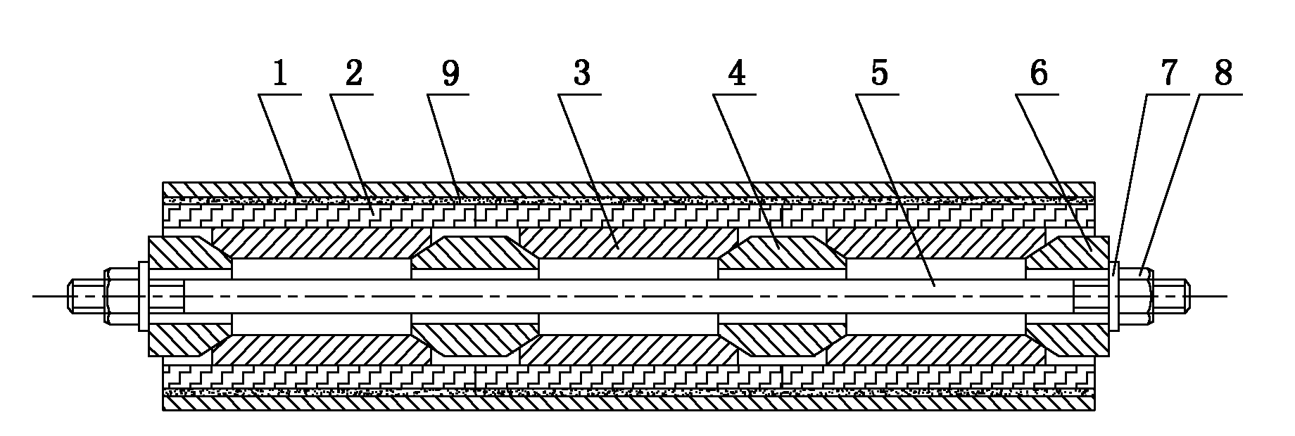
[0030] figure 2 It is a specific embodiment of th...


PUM


Abstract

The invention relates to a high temperature vacuum brazing clamp for an internally finned tube. The clamp consists of a supporting guide tube, an inner supporting cone, a core tube, an end head supporting cone, a gasket and a nut, wherein the supporting guide tube consists of a plurality of tube segments which are formed by uniformly cutting a circular tube along the axial direction; when an external force is applied to the nut, the supporting guide tube can move along the inclined planes of the inner supporting cone and the end head supporting cone so as to uniformly stretch the tube segments of the supporting guide tube along the radial direction; and inner fins can be gradually and closely attached to the inner wall of an outer tube under the action of the uniform tension of the supporting guide tube. The clamp of the invention can apply uniform tension to the internally finned tube during the high temperature brazing process, reduce the distance for the weld joint, improve the ratio of welding area, improve the strength and the plasticity of the brazing joint and reduce the thermal contact resistance so as to meet the requirements for the use of the internally finned tube in a high temperature heat exchanger; and meanwhile, the clamp has a simple structure and convenient assembly and is suitable for large-scale industrial production.

Description

technical field [0001] The invention relates to an inner finned tube brazing fixture and its manufacturing process, in particular to a high temperature inner finned tube used in the fields of high temperature waste heat recovery such as chemical industry, metallurgy, glass manufacturing, municipal solid waste incineration and biomass incineration. A jig required for vacuum brazing. Background technique [0002] With the increasing shortage of energy, the world needs more efficient energy power systems, and efficient energy power systems often require higher operating temperatures. At the same time, the world is paying more and more attention to emission reduction and energy saving. Therefore, high-temperature heat exchangers have broad market demand in high-temperature waste heat recovery fields such as chemical industry, metallurgy, glass manufacturing, municipal solid waste incineration and biomass incineration, such as solid oxide fuel cells, external combustion combined ...

Claims


Application Information

Patent Timeline
IPC IPC(8): B23K3/08B23K1/008
Inventor 王秋旺马挺王士元曾敏吉彦鹏
Owner XI AN JIAOTONG UNIV
Why Eureka
Try Eureka