

Sludge treating system
A sludge treatment and sludge technology, applied in sludge treatment, biological sludge treatment, water/sludge/sewage treatment, etc., can solve problems such as mesh blockage and heat exchange efficiency reduction, achieve effective heat treatment, and simple structure , not easy to reduce the effect of heat exchange efficiency
- Summary
- Abstract
- Description
- Claims
- Application Information
AI Technical Summary
Problems solved by technology
Method used
Image

Examples
Embodiment Construction
[0037] Hereinafter, one Embodiment of the sludge processing system of this invention is demonstrated in detail using drawing.
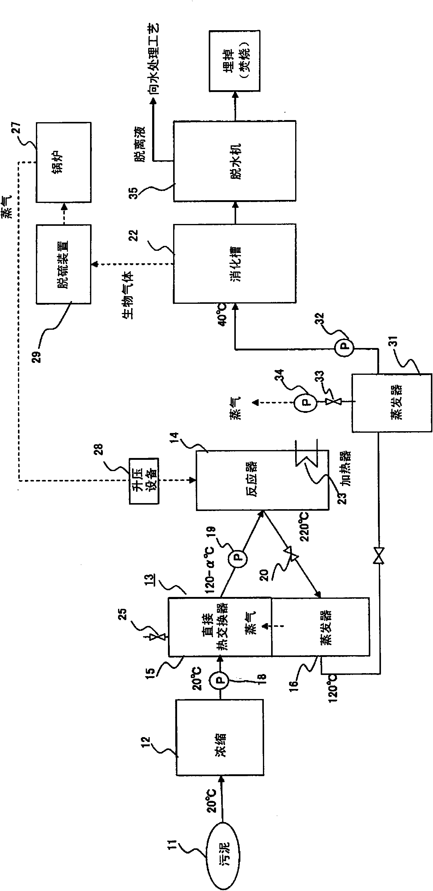
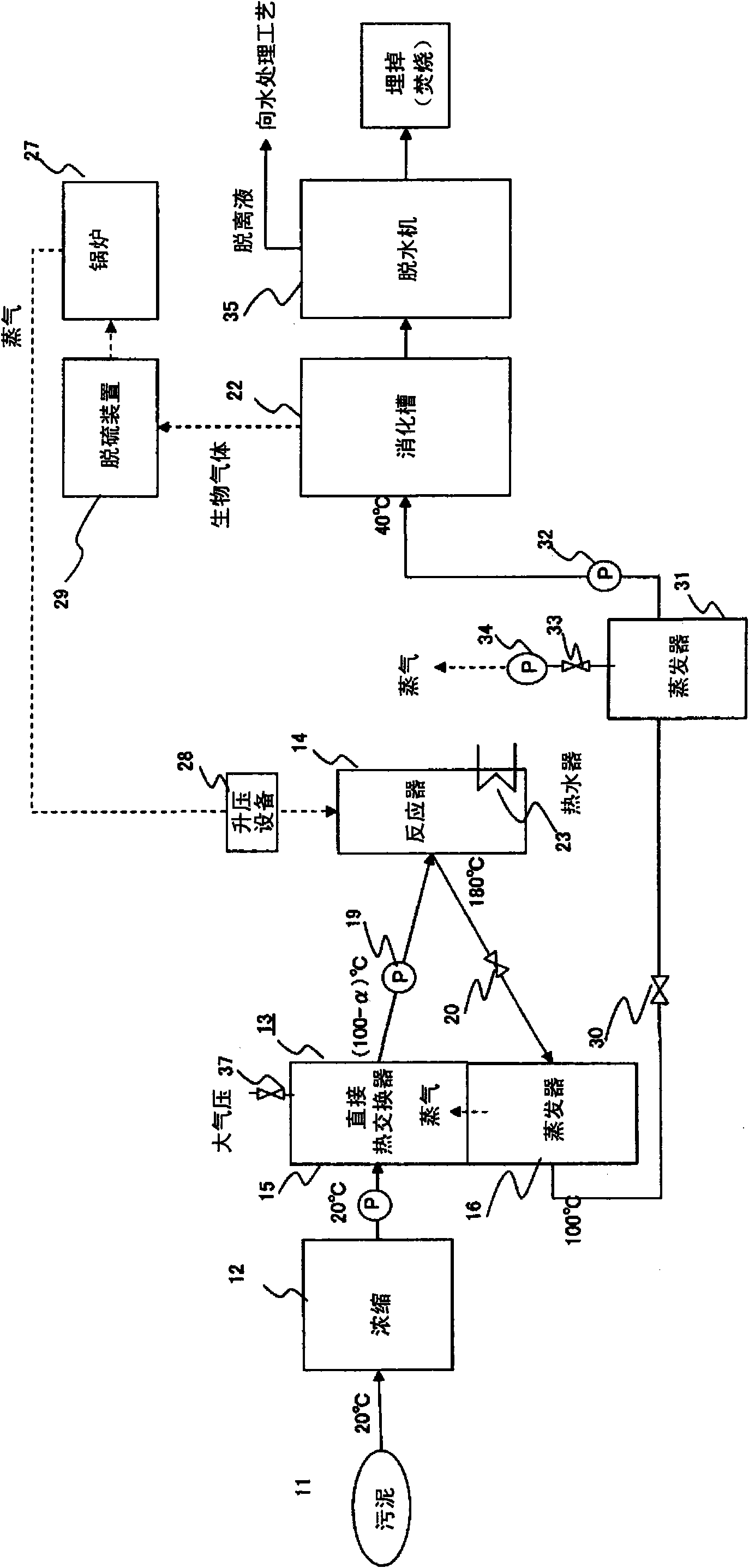
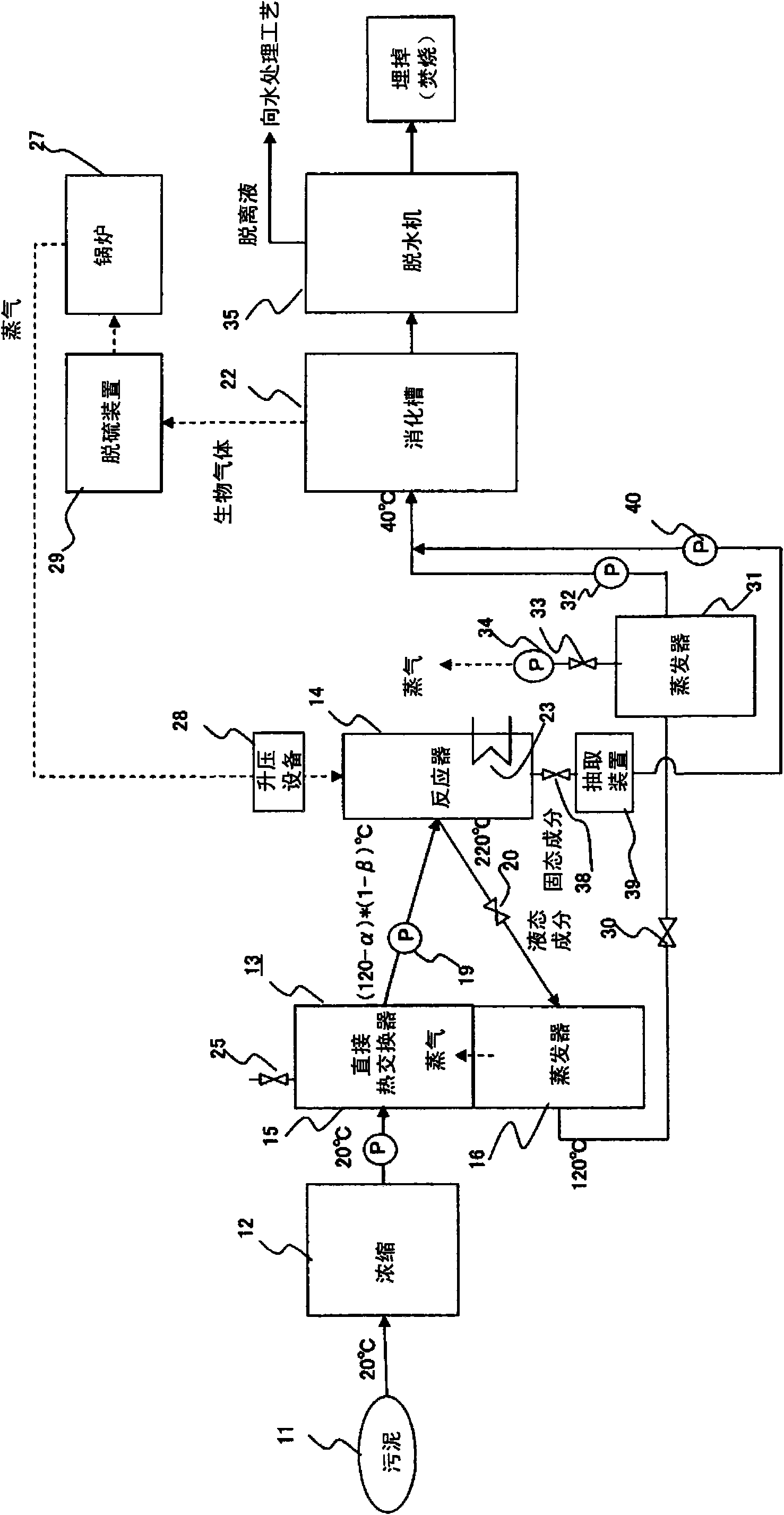
[0038] figure 1 is a block diagram showing the structure of this embodiment. figure 1 The sludge treatment system shown has a concentrator 12 for concentrating sludge 11 containing many organic substances to be treated, a preheating device 13 for the concentrated sludge, and preheating the preheated sludge under a predetermined pressure. Reactor 14 for heating and heat treatment.
[0039] The preheating device 13 is, for example, as shown in Japanese Patent Application Laid-Open No. 2007-21300, in which a direct heat exchanger unit 15 is arranged on the upper part of a common container, and an evaporator unit 16 is arranged on the lower part to integrate them, so that the evaporation at the lower part The high-temperature steam generated in the tank part 16 directly contacts and warms the sludge introduced into the upper direct heat exchanger part 1...
PUM
 Abstract
Description
Claims
Application Information