Soot blower

A technology of soot blower and soot blowing pipe, which is applied in the directions of combustion product treatment, combustion method, and solid residue removal, etc. The effect of eliminating the dead angle of soot blowing, reducing the operating failure rate and improving the soot blowing effect

Active Publication Date: 2010-09-29
CHINA PETROCHEMICAL CORP +1
View PDF11 Cites 17 Cited by
  • Summary
  • Abstract
  • Description
  • Claims
  • Application Information

AI Technical Summary

Problems solved by technology

[0004] The purpose of the present invention is to provide a soot blower to solve the problems of the existing soot blowers such as high failure rate in operation, dead angle in the soot blowing area, poor soot blowing effect, etc.

Method used


Image

  • Soot blower
  • Soot blower
  • Soot blower

Examples


Embodiment Construction

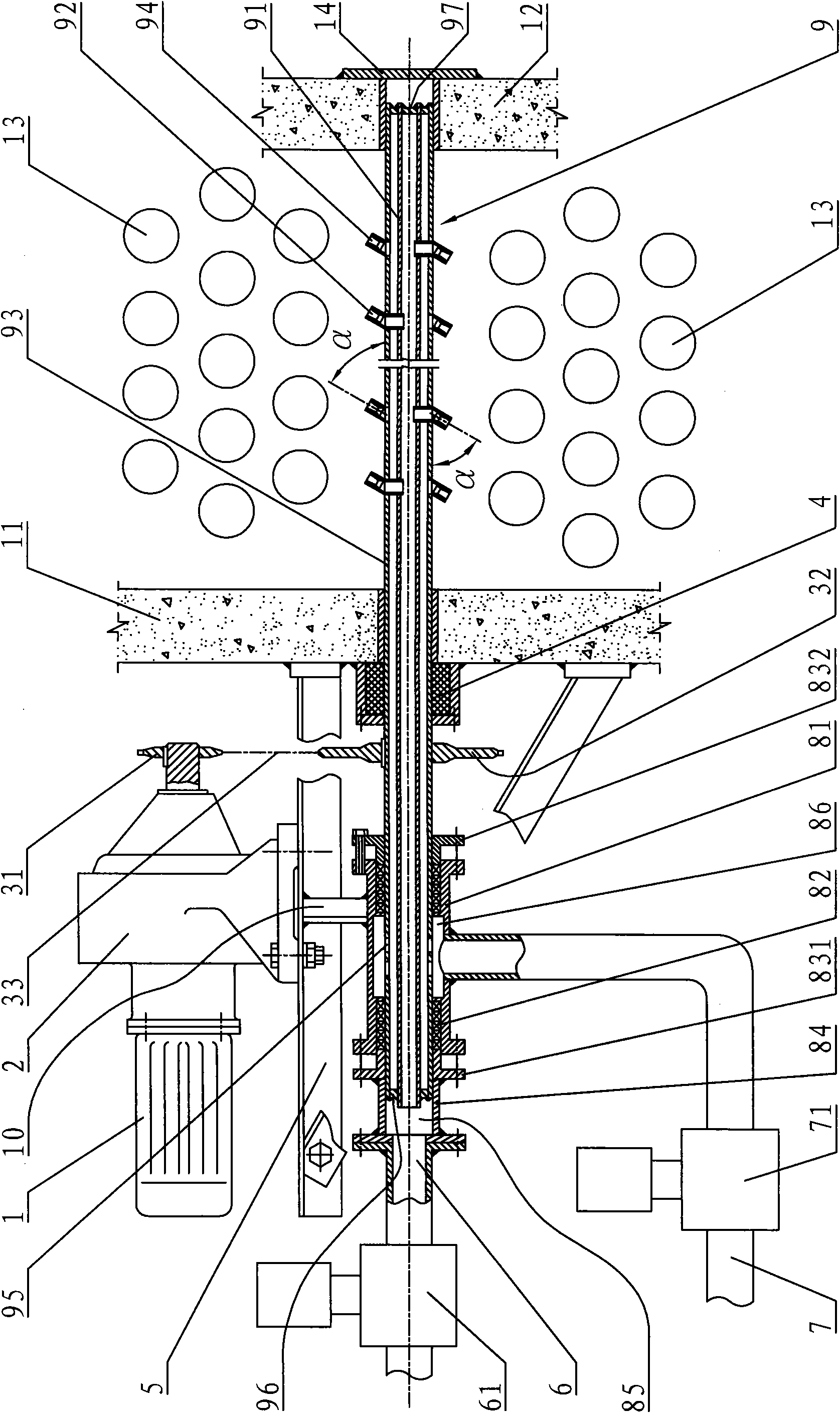
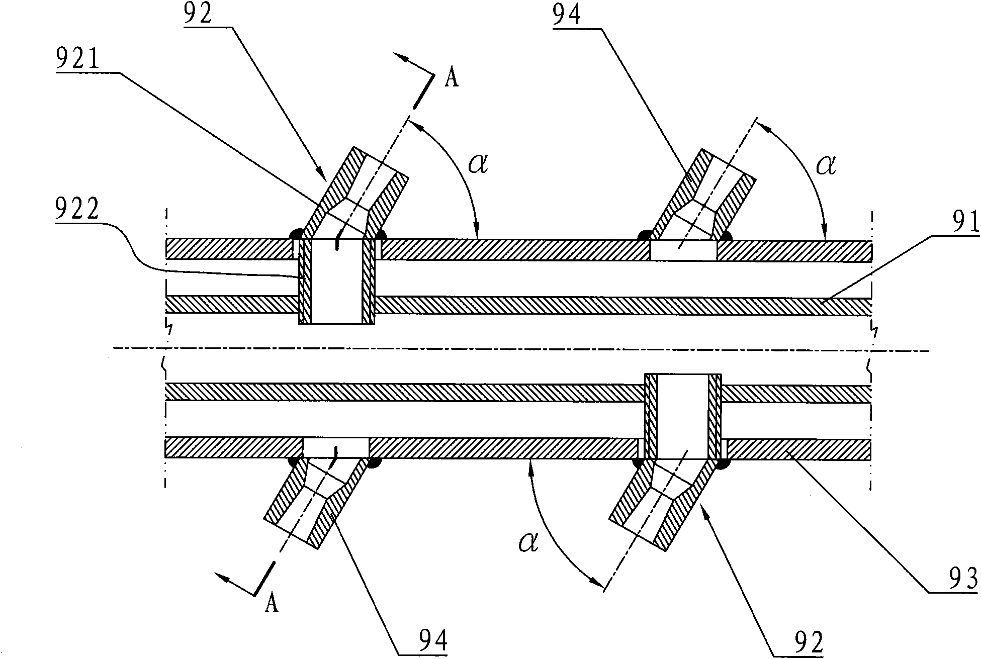
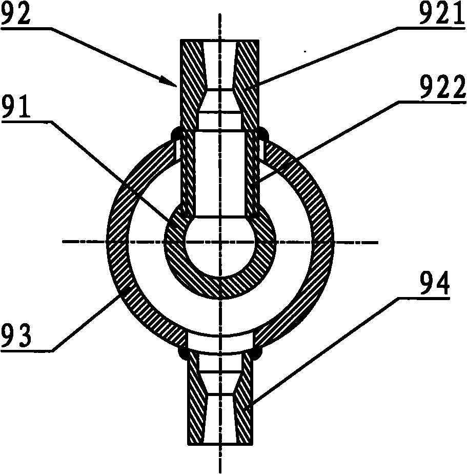
[0013] see figure 1 , figure 2 and image 3 , The soot blower of the present invention is provided with an air intake system, a transmission system, a soot blowing pipe 9 and a support 5 . The transmission system includes a motor 1, a reducer 2, and a chain transmission device. The chain drive is made up of driving sprocket 31 , driven sprocket 32 ​​and chain 33 . The driving sprocket 31 is connected with the output shaft of the reducer 2, and the driven sprocket 32 ​​is connected with the outer soot blowing pipe 93, both of which can be connected by means of flat key connection; the driven sprocket 32 ​​can also be welded on the outer soot blowing pipe 93 . The diameter of the driven sprocket 32 ​​is generally larger than that of the driving sprocket 31 . The speed reducer 2 of the soot blower is a cycloidal pin wheel speed reducer, which can be of various commonly used types in the industry. The present invention adopts the cycloid reducer because its deceleration rat...


PUM


Abstract

The invention discloses a soot blower in order to solve the problems that the existing soot blower has higher operating failure rate, unreachable blowing area and poor blowing effect. The transmission system of the soot blower of the invention comprises a motor, a reducer and a chain transmission device, wherein the reducer is particularly a cycloidal pin-wheel reducer. The soot blower is provided with an internal soot blower and an external soot blower, and an internal soot blower nozzle and an external soot blower nozzle are arranged on the internal soot blower and the external soot blower respectively; the inclined section of the internal soot blower nozzle is arranged in a way that the inclined section thereof is inclined relative to the axis of the soot blower; an air inlet is formed on the inlet section of the external soot blower; the air inlet system of the soot blower is provided with an air inlet tube, and a second air inlet chamber arranged in the middle of the air inlet tube is communicated with the air inlet and a second air inlet pipe; a first air inlet chamber is arranged at the end part of the inlet section of the internal soot blower and communicated with the end part of the inlet section of the internal soot blower and the first air inlet pipe; a first electromagnetic valve is arranged on the first air inlet pipe; and a second electromagnetic valve is arranged on the second air inlet pipe. The invention is mainly applicable to tubular heating furnaces in the field of petroleum refining and petroleum chemical engineering.

Description

technical field [0001] The invention relates to a soot blower, in particular to a soot blower used for cleaning the furnace tube in the convection section of a tubular heating furnace and the soot deposited on the heat exchange tube in the air preheater. Background technique [0002] In the field of petroleum refining and petrochemical industry, with the change of crude oil properties and the increase of sulfur content, the problem of fouling and fouling on the furnace tube in the convection section of the tubular heating furnace and the heat exchange tube in the air preheater is becoming more and more serious , affecting the heat transfer effect. In the case of severe dust accumulation, the heat transfer capacity of the furnace tube and heat exchange tube will be reduced by about 30% to 50%; Refining and petrochemical enterprises account for 30% to 40% of the total energy consumption. How to effectively reduce the dust accumulation on the furnace tube and heat exchange tu...

Claims


Application Information

Patent Timeline
Patent Type & Authority Applications(China)
IPC IPC(8): F23J3/02
Inventor 郜建松李绍明杨利然张海燕孙志钦孟庆凯高晓红高跃成王作红张玉玲黄进焕段彦明
Owner CHINA PETROCHEMICAL CORP
Why Eureka
Try Eureka