Solution dehumidifying fresh air handling unit combining heat pump drive and evaporative cooling

A technology of evaporative cooling and fresh air unit, applied in space heating and ventilation, details of space heating and ventilation, energy recovery system for ventilation and heating, etc., can solve the problem of affecting the performance of the heat pump system solution dehumidification unit and reducing the performance of the solution dehumidification unit , Condensation temperature rise and other issues, to achieve the effect of improving energy utilization efficiency, improving indoor air quality, and increasing humidity

Active Publication Date: 2010-09-29
TSINGHUA UNIV +1
View PDF3 Cites 22 Cited by
  • Summary
  • Abstract
  • Description
  • Claims
  • Application Information

AI Technical Summary

Problems solved by technology

But in many cases, no indoor exhaust can be used. Patent ZL200610012268.2 discloses a heat-driven solution fresh air treatment unit that uses cooling water as a cooling source. It installs an evaporative cooling device (using cooling water as a cooling source) Take away the excess heat from the condenser, but because the heat from the condenser is only taken away by the solution regeneration system, the condensation temperature is very high, which significantly reduces the performance of the solution dehumidification unit
In addition, in the above three patents, the heat dissipation of the condenser is greater than the heat required for the concentration and regeneration of the solution in the system. If the excess heat of this part of the condenser is not eliminated, the condensation temperature will continue to rise, which will significantly affect the heat pump. System and overall solution dehumidification unit performance

Method used


Image

  • Solution dehumidifying fresh air handling unit combining heat pump drive and evaporative cooling
  • Solution dehumidifying fresh air handling unit combining heat pump drive and evaporative cooling
  • Solution dehumidifying fresh air handling unit combining heat pump drive and evaporative cooling

Examples


Embodiment 1

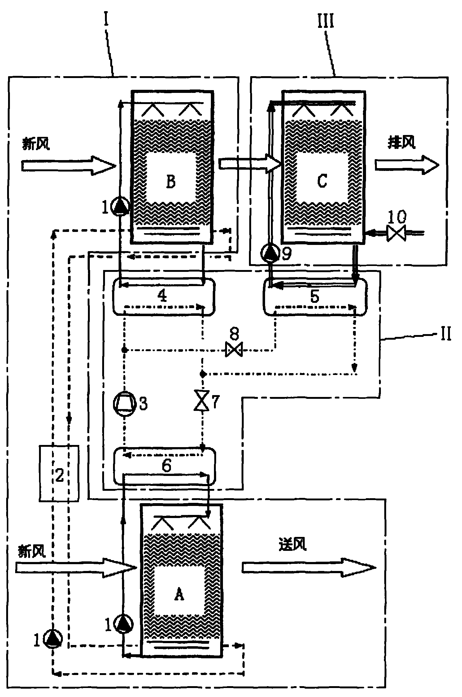
[0018] Such as figure 1 As shown, the fresh air unit in this embodiment includes a solution circulation system I, a heat pump system II and an evaporative cooling water system III.

[0019] The solution circulation system I includes a dehumidification module A, a regeneration module B and a solution circulation pump 1. The dehumidification module A and the regeneration module B are connected through the solution circulation pump 1 to form an interstage solution circulation loop, and the dehumidification module A and the regeneration module B A plate heat exchanger 2 is arranged on the interstage solution circulation loop.

[0020] The heat pump system II includes a compressor 3, a condenser 4 that exchanges heat with the solution, a condenser 5 that exchanges heat with water, an evaporator 6, a throttle valve 7 and a solenoid valve 8, in which the compressor 3, the condenser 4, the throttle Valve 7 and evaporator 6 are sequentially connected to form a circulation loop for hea...

Embodiment 2

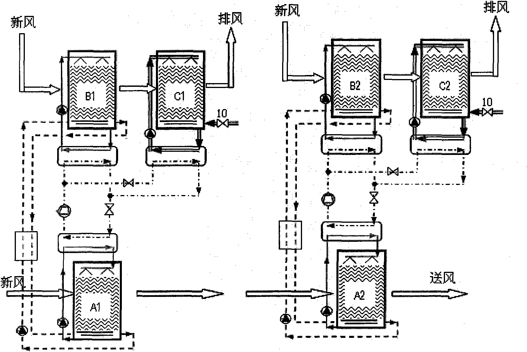
[0025] Such as figure 2 As shown, the difference between this embodiment and Embodiment 1 is that the fresh air unit of this embodiment adopts the mode of regenerative fresh air parallel connection, which includes two parallel fresh air units, and the structure of the two fresh air units is the same as that of Embodiment 1, wherein One fresh air for regeneration passes through the regeneration module B1 and the evaporative cooling module C1 in sequence, and the other fresh air for regeneration passes through the regeneration module B2 and the evaporative cooling module C2 in sequence.

[0026] In the above embodiment, the number of fresh air units connected in parallel can also be more than two, and the specific number can be determined according to the usage on site.

Embodiment 3

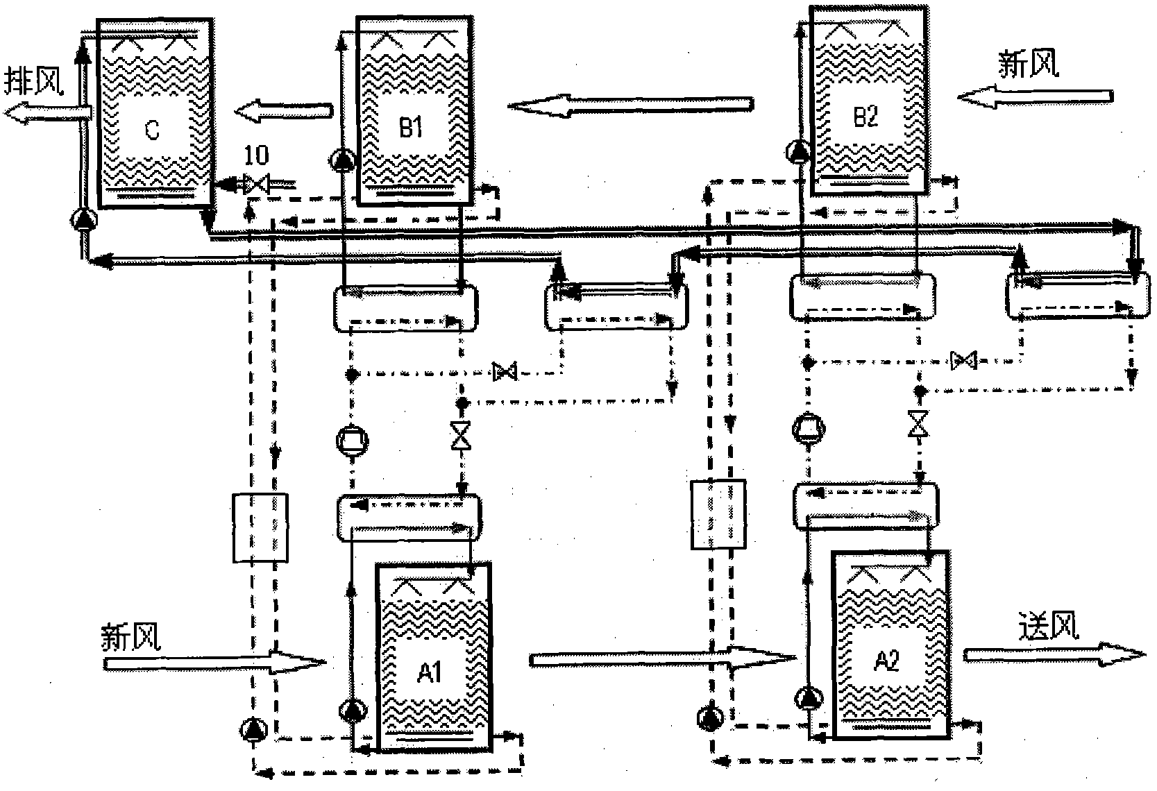
[0028] Such as image 3 As shown, the difference between this embodiment and Embodiment 1 is that the fresh air unit of this embodiment adopts the mode of regenerative fresh air series, which includes two series-connected solution circulation systems I, two series-connected heat pump systems II and an evaporative cooling water System III, and the condenser 5 in the two heat pump systems II and the evaporative cooling module C in the evaporative cooling water system III are connected in series to form a circulation loop for heat exchange with the refrigerant. The outdoor fresh air first passes through the dehumidification modules A1 and A2 in sequence, and then Pass through regeneration modules B2 and B1 in sequence.

[0029]In the above embodiment, the number of the solution circulation system I and the heat pump system II connected in series can also be more than two, and the specific number can be determined according to the usage on site.

[0030] Analyze the flow process ...


PUM


Abstract

The invention relates to a solution dehumidifying fresh air handling unit combining heat pump drive and evaporative cooling, which is characterized by comprising a solution circulating system, a heat pump system and an evaporative cooling water system, wherein the solution circulating system comprises an interstage solution circulation loop formed by connecting a dehumidifying module, a regeneration module and a solution circulating pump; the heat pump system comprises a solution heat exchange circulation loop formed by connecting a compressor, a first condenser, a throttle valve and an evaporator sequentially and a water heat exchange circulation loop formed by connecting the compressor, a solenoid valve, a second condenser, the throttle valve and the evaporator sequentially; the first condenser and the heat-exchange end of the evaporator are respectively connected with the regeneration module and the dehumidifying module through the solution circulating pump to form two intrastage solution circulation loops; the evaporative cooling water system comprises an evaporative cooling module, a water circulating pump and a water replenishing valve; and the evaporative cooling module is connected with the second condenser through the water circulating pump to form a circulation loop performing heat exchange with refrigeration working media. The solution dehumidifying fresh air handling unit can be widely applied to occasions without indoor ventilation for use.

Description

technical field [0001] The invention relates to a fresh air unit, in particular to a solution dehumidification fresh air unit combined with heat pump driving and evaporative cooling. Background technique [0002] At present, most of the existing air conditioners adopt the condensation dehumidification treatment method, and use the refrigerator to prepare low-temperature frozen water to reduce the air temperature below the dew point, thereby realizing the dehumidification treatment process for the fresh air. Since the required cold source temperature is very low (lower than the dew point temperature of the air), the evaporation temperature of the refrigerator is reduced, which seriously affects the coefficient of performance of the refrigerator. Moreover, the condensed water produced by condensation dehumidification is easy to breed mold and seriously affect the indoor air quality. The solution dehumidification method uses a salt solution with hygroscopic properties as the w...

Claims


Application Information

Patent Timeline
Patent Type & Authority Applications(China)
IPC IPC(8): F24F3/14F24F12/00F24F13/30
Inventor 刘晓华张海强张涛江亿陈晓阳
Owner TSINGHUA UNIV
Why Eureka
Try Eureka