Microneedles array, die casting method for manufacturing microneedle array and die for manufacturing microneedle array

A microneedle array and microneedle technology, applied in the field of microneedle arrays, can solve the problems of non-reusable, poor practicability of microneedle arrays, and high cost of microneedle arrays

Active Publication Date: 2010-10-13
THE HONG KONG POLYTECHNIC UNIV
View PDF1 Cites 41 Cited by
  • Summary
  • Abstract
  • Description
  • Claims
  • Application Information

AI Technical Summary

Problems solved by technology

Because the material silicon of this kind of microneedle array is relatively expensive, this makes the cost of the microneedle array too high, and the microneedle array is a disposable medical product and cannot be reused. The practicability of the microneedle array of this kind of silicon material is poor
At the same time, the microneedle array of this silicon material is made by a photoetching process. The photoetching process is relatively complicated, and only a single product can be produced at a time. It is difficult to achieve mass production, and the process cost is high.

Method used


Image

  • Microneedles array, die casting method for manufacturing microneedle array and die for manufacturing microneedle array
  • Microneedles array, die casting method for manufacturing microneedle array and die for manufacturing microneedle array
  • Microneedles array, die casting method for manufacturing microneedle array and die for manufacturing microneedle array

Examples


Embodiment Construction

[0077] Specific embodiments of the present invention will be described in detail below. It should be noted that the embodiments described here are for illustration only, and are not intended to limit the present invention.

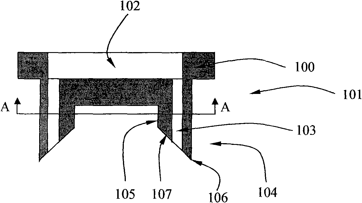
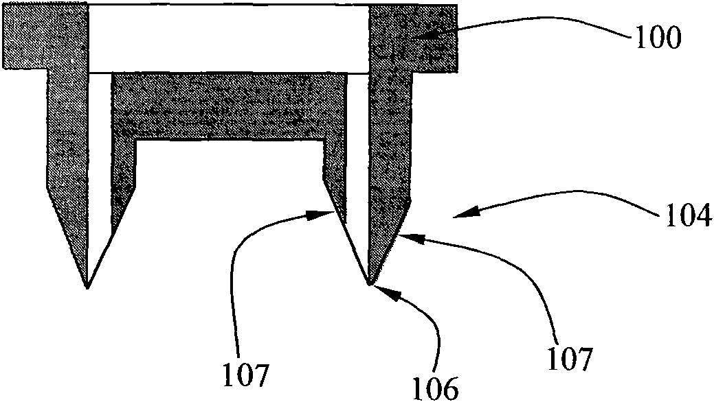
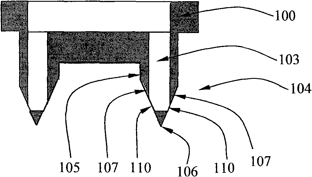
[0078] Such as figure 1 , Figure 1A , Figure 1B , Figure 1C and Figure 1D As shown, the microneedle array of the first embodiment of the present invention includes a relatively small number of microneedles, and its structure includes a base 100 and several microneedles 101 arranged centrally or axisymmetrically formed integrally with the base 100 . Wherein the base 100 has a liquid storage cavity 102 for storing medical liquid or interstitial fluid. The microneedle 101 has a microneedle hole 103 communicating with the liquid storage cavity 102 . The microneedle 101 includes a needle body part 105 and a peak part 104 integrally formed with the base 100 . The end surface of the peak portion 104 is a slope 107 forming an acute angle with the center...


PUM

PropertyMeasurementUnit
lengthaaaaaaaaaa

Abstract

The invention provides a microneedles array, a method for manufacturing the microneedles array and a die for manufacturing the microneedles array. The microneedles array comprises a base and a plurality of microneedles which are integrated with the base, wherein a liquid storage cavity is arranged in the base, and each microneedle are provided with micro-pinholes which are communicated with the liquid storage cavity; the microneedles array is made of plastics, composite materials, and ceramics or metal materials by injection molding; and each microneedle has at least one inclined surface which is inclined towards the central line of the microneedle, and the outlet of each micro-pinhole is positioned on at least one inclined surface, so that the end of the outlet of the microneedle forms a pinnacle part. The die specialized for the invention comprises an upper die, a middle die and a lower die, wherein the middle die and the lower die are provided with cavities for forming the microneedles; and the upper die and the middle die are provided with grooves for forming the base. The three-plate die of the invention can be used for conveniently manufacturing the microneedles array with the pinnacles. Since the stripping process in the injection molding method is carried out step by step, the method has the advantages of small die drawing resistance and low manufacturing cost.

Description

technical field [0001] The invention relates to a microneedle array with microneedle holes, a method for manufacturing the microneedle array and a special mold used in the method. Background technique [0002] The outermost skin layer of the human body, such as the stratum corneum, is the most beneficial biological barrier protection layer of the human body. The stratum corneum has excellent electrical insulation, which can effectively prevent external fluid from entering the subcutaneous tissue, and can also prevent the interstitial fluid from seeping out. At present, in the field of biomedicine, subcutaneous administration (that is, direct administration of medicinal liquid to the subcutaneous tissue below the stratum corneum) and collection of test samples from the subcutaneous interstitial fluid are becoming increasingly important for treating and diagnosing diseases. Both procedures require the use of needles or microneedle arrays that can penetrate the stratum corneum...

Claims


Application Information

Patent Timeline
Patent Type & Authority Applications(China)
IPC IPC(8): A61M37/00B29C45/00B29C33/44B29C45/26
CPCA61M37/0015A61M2037/0053A61M2037/0023
Inventor 徐雁容启亮
Owner THE HONG KONG POLYTECHNIC UNIV
Why Eureka
Try Eureka