
Method for improving strength of ceramic soldered joint by in-situ self-generated TiB whiskers

A brazed joint, in-situ self-generating technology, which is applied in the field of preparation of ceramic brazed joints, can solve the problems such as the reinforcement phase and the matrix are not easily wetted, the joint stress is large, segregation and the like

Inactive Publication Date: 2012-02-08
上海迪登科技发展有限公司
View PDF0 Cites 0 Cited by
  • Summary
  • Abstract
  • Description
  • Claims
  • Application Information

AI Technical Summary

Problems solved by technology

[0003] The present invention aims at the problem that the joint stress of the existing ceramic active brazing method is large, the strength is low, and the reinforcing phase directly added to the active brazing material is easy to segregate in the joint, and the reinforcing phase and the matrix are not easy to wet. And provide a kind of in-situ self-generated TiB whisker to improve the method of ceramic brazed joint intensity

Method used

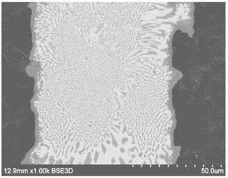
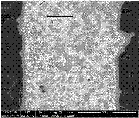
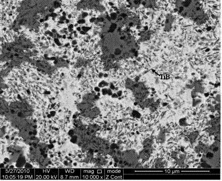

Image

  • Method for improving strength of ceramic soldered joint by in-situ self-generated TiB whiskers
  • Method for improving strength of ceramic soldered joint by in-situ self-generated TiB whiskers
  • Method for improving strength of ceramic soldered joint by in-situ self-generated TiB whiskers

Examples


specific Embodiment approach 1

[0008] Specific implementation mode 1: A method for improving the strength of ceramic brazing joints by in-situ self-generated TiB whiskers in this embodiment is carried out according to the following steps: 1. Weigh 40% to 75% of Ag powder, 20% to 40% by mass percentage % Cu powder, 1% ~ 10% TiB 2 Powder and 4%~10% TiH 2 powder and put it into a ball mill, and under the protection of Ar gas, ball mill at a speed of 300 rpm to 350 rpm for 1h to 5h to obtain a composite solder; 2. Clean and dry the surface of the ceramic part to be welded with acetone 3. Take by weighing the composite solder and the binder obtained in step 1 by the volume ratio of the composite solder and the binder, and mix the composite solder and the binder evenly, and coat it on the On the surface to be welded of the ceramic part processed in step 2, the thickness of the coating layer is 100 μm to 300 μm to obtain the piece to be welded; 4. Put the piece to be welded obtained through step 3 into a vacuum b...

specific Embodiment approach 2

[0010] Specific embodiment two: the difference between this embodiment and specific embodiment one is: the binding agent described in the step 3 consists of 1% glycerol, 3% distilled water and 96% hydroxyethyl cellulose by mass percentage mixed. Other steps and parameters are the same as in the first embodiment.

specific Embodiment approach 3

[0011] Specific embodiment three: the difference between this embodiment and specific embodiment one or two is that in step one, 41% to 71% of Ag powder, 22% to 35% of Cu powder, 2% to 8% TiB 2 powder and 5% to 8% TiH 2 pink. Other steps and parameters are the same as those in Embodiment 1 or 2.


PUM

PropertyMeasurementUnit
thicknessaaaaaaaaaa
thicknessaaaaaaaaaa
shear strengthaaaaaaaaaa

Abstract

The invention discloses a method for improving the strength of a ceramic soldered joint by in-situ self-generated TiB whiskers, and relates to a preparation method for the ceramic soldered joint. The method solves the problems that a conventional ceramic activity soldering method has high joint stress and low strength and an enhancement phase in a method for directly adding the enhancement phase into an active solder is easy to segregate in the joint and is not easy to wet with matrix. The method comprises the following steps of: ball-milling Ag, Cu, TiB2 and TiH2 powder and mixing the ball-milled powder and adhesive uniformly, coating the mixture on a to-be-soldered surface of a ceramic piece to obtain a to-be-soldered piece, putting the to-be-soldered piece into a vacuum soldering furnace, and performing vacuum soldering treatment on the to-be-soldered piece to obtain the ceramic soldered joint of the in-situ self-generated enhancement phase. The in-situ self-generated TiB whiskers have good compatibility with the joint matrix and are distributed uniformly, and the compressive shearing strength of the ceramic soldered joint is 70 to 165MPa and is improved by 95 to 195 percent compared with the strength of a joint without the enhancement phase.

Description

technical field [0001] The invention relates to a method for preparing a ceramic brazing joint. Background technique [0002] Since ceramic connection can overcome the inherent brittleness and difficulty of processing of ceramic materials, it can meet the needs of aerospace, metallurgy and other fields for large-sized and complex-shaped ceramic parts. Therefore, the development and application of ceramic connection technology has attracted much attention. The traditional active brazing method of ceramics is to add active elements, such as Ti, Zr or Hf, to the brazing material. The thermal matching of the welded joint is poor, and there are shortcomings of high joint stress and low strength; in addition, the method of directly adding the reinforcing phase to the active solder is to add a high Young's modulus and a small linear expansion coefficient to the active solder. Ceramic particles, hard metal particles, and fibers are used as the reinforcing phase. This method can re...

Claims


Application Information

Patent Timeline
Patent Type & Authority Patents(China)
IPC IPC(8): C04B37/00
Inventor 林铁松何鹏杨敏旋
Owner 上海迪登科技发展有限公司
Learn More