Constant pressure oil outlet valve

A technology of oil outlet valve and oil outlet valve seat, which is applied in the direction of engine components, fuel injection pumps, machines/engines, etc., can solve the problem of ineffective control of the initial pressure of throttling fuel, low sensitivity of component action coordination, unsatisfactory and Perfection and other issues to achieve the effect of avoiding excessive enhancement, novel design and reasonable structure

Inactive Publication Date: 2010-10-20
宁波舜田良源油嘴油泵有限公司
View PDF5 Cites 15 Cited by
  • Summary
  • Abstract
  • Description
  • Claims
  • Application Information

AI Technical Summary

Problems solved by technology

The oil outlet valve body, the oil outlet valve seat, the oil outlet valve spring and the reducing container form a first one-way valve, and a second one-way valve opposite to the first one-way valve is installed in the inner cavity of the oil outlet valve body , this kind of fuel delivery valve utilizes the pressure reducing container installed on the top of the inner cavity to realize the change of the internal volume of the fuel delivery valve to control the fuel pressure. It can also prevent the bad injection of the fuel injector and improve the regularity of fuel, but its structure is complex and the parts The sensitivity of action coordination is not high, and the throttling at the flow section of the oil delivery valve and the initial pressure of the fuel cannot be effectively controlled, so it is not ideal and perfect

Method used


Image

  • Constant pressure oil outlet valve
  • Constant pressure oil outlet valve
  • Constant pressure oil outlet valve

Examples


Embodiment Construction

[0015] The present invention will be further described in detail below in conjunction with the specific embodiments of the accompanying drawings.

[0016] Figure 1 to Figure 4 It is a schematic diagram of the structure of the present invention.

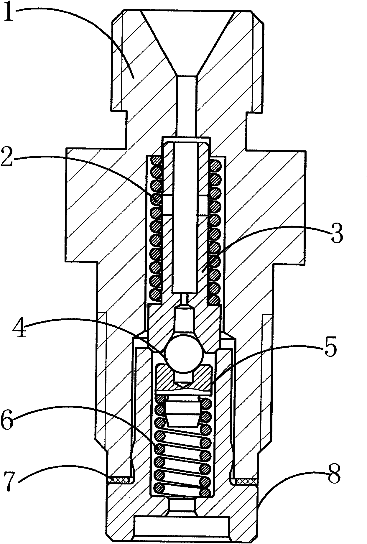
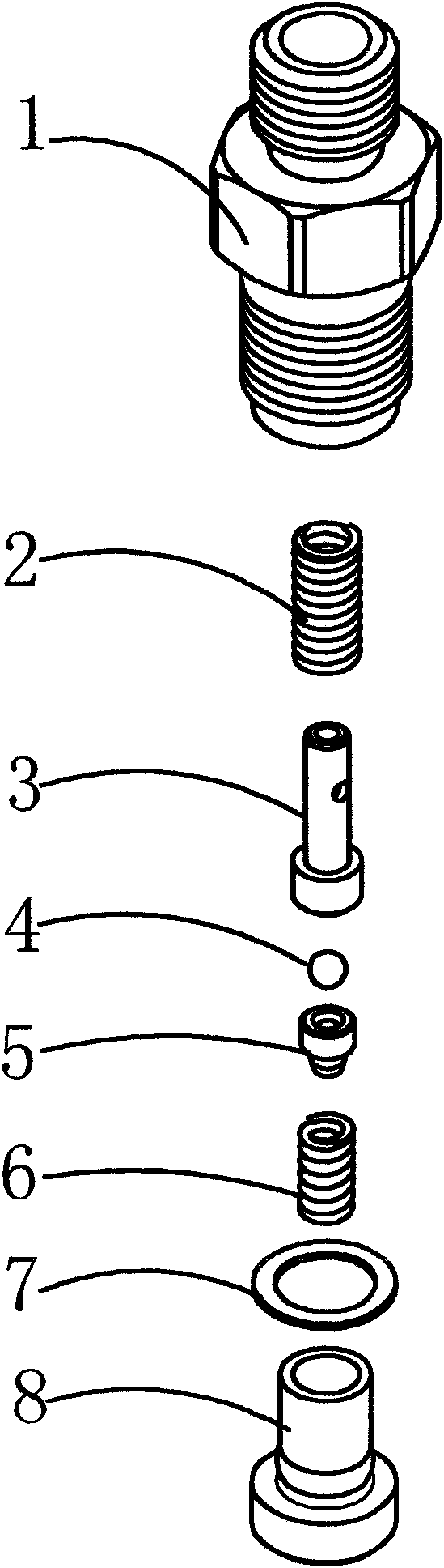
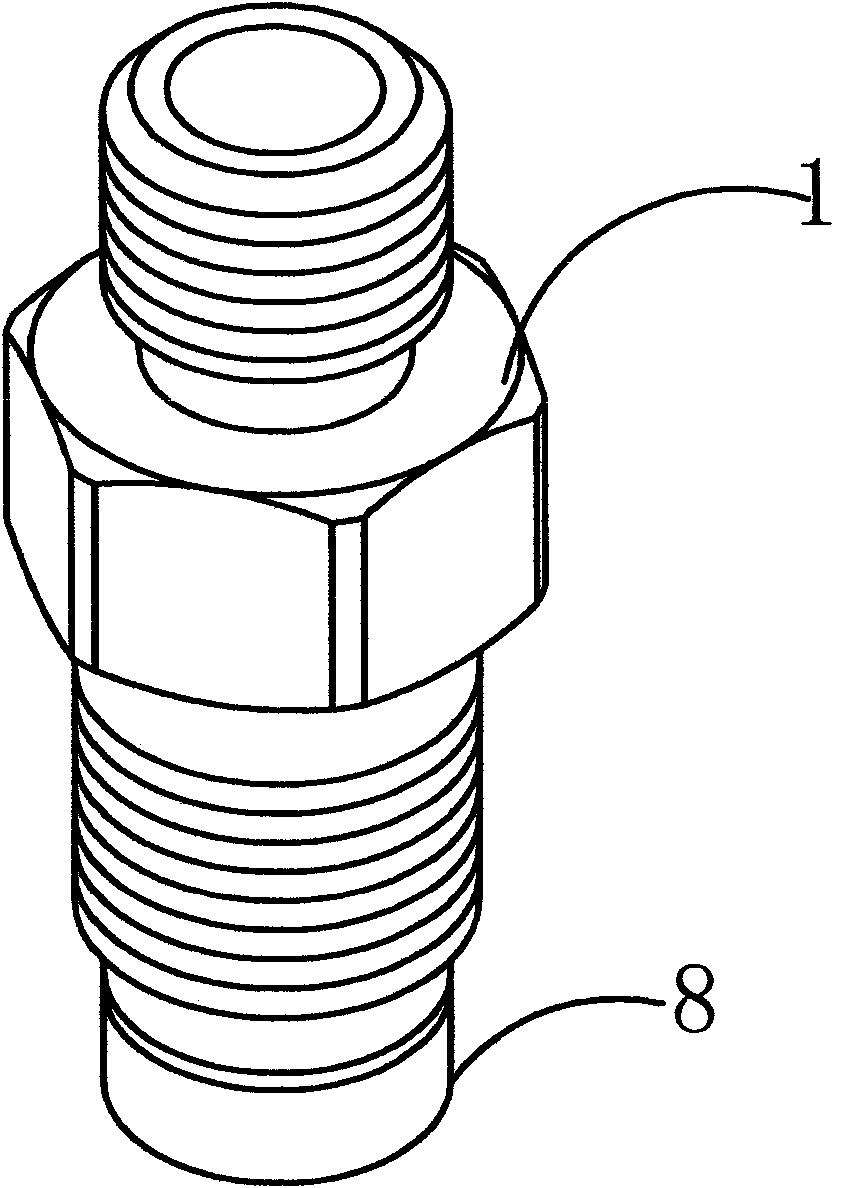
[0017] The reference signs are: oil outlet valve tight seat 1, lift limiting chamber 1a, oil outlet valve spring 2, oil outlet valve core 3, outer spherical surface 3a, oil inlet 3b, oil discharge orifice 3d, Protruding rafter column 31, groove 32, steel ball 4, spring seat 5, pressure relief valve spring 6, sealing gasket 7, oil outlet valve seat 8, inner spherical surface 8a.

[0018] Such as Figure 1 to Figure 4 As shown, the equal-pressure oil outlet valve of the present invention includes an oil outlet valve tight seat 1, an oil outlet valve spring 2 installed in the oil valve tight seat 1, an oil outlet valve core 3, and an oil outlet valve seat 8 and assembled in sequence The steel ball 4, the spring seat 5, and the pressu...


PUM


Abstract

The invention relates to the manufacturing technology of a single cylinder high speed diesel engine with a small cylinder diameter, in particular to a constant pressure oil outlet valve suitable for a diesel engine fuel oil system. The constant pressure oil outlet valve comprises an oil outlet valve tightening seat, an oil outlet valve spring, an oil outlet valve core, an oil outlet valve seat, a steel ball, a spring seat and a pressure relief valve spring, wherein the oil outlet valve spring, the oil outlet valve core and the oil outlet valve seat are mounted in the oil outlet valve tightening seat, the steel ball, the spring seat and the pressure relief valve spring are sequentially assembled in the oil outlet valve tightening seat, the oil outlet valve tightening seat is provided with a lift-range limiting cavity capable of controlling the lift-range of the oil outlet valve, the oil outlet valve core and the oil outlet valve seat are tangentially matched to form a one-way oil supply valve, the oil outlet valve core and the steel ball are tangentially matched to form a constant pressure relief valve, and the lift-range limiting cavity can influence the throttle flow and the initial pressure of the fuel oil in the oil outlet valve through controlling the jumping height of the oil outlet valve core. The constant pressure oil outlet valve has the functions of limiting the lift-range and relieving pressure, can eliminate the secondary injection, the unstable injection generated easily due to low speed and the cavitation erosion easily occurring to a high pressure chamber, and the like, and has the characteristics of simple structure, skillful process, favorable performance, low fuel oil consumption rate, low discharge, stable injection, an the like.

Description

technical field [0001] The invention relates to a mechanical product, in particular to the manufacturing technology of a single-cylinder small-bore high-speed diesel engine, in particular to an equal-pressure oil outlet valve suitable for the fuel system of the diesel engine. Background technique [0002] The oil outlet valve assembly of the single-cylinder high-speed diesel engine fuel injection pump involved in the prior art has a structure including an oil outlet valve tight seat, an oil outlet valve spring, an oil outlet valve core, and an oil outlet valve seat; it is suitable for single-cylinder small-bore high-speed Diesel engines, with the development of diesel engines, the strengthening and strict restrictions on emissions require the fuel supply system to provide higher injection pressure and fuel injection rate. The traditional equal-volume oil outlet valve is prone to secondary injection at high speed and low speed. Unstable injection and cavitation in the high-pr...

Claims


Application Information

Patent Timeline
Patent Type & Authority Applications(China)
IPC IPC(8): F02M59/46
Inventor 周书田
Owner 宁波舜田良源油嘴油泵有限公司
Why Eureka
Try Eureka