
Airborne laser radar pitch angle deviation real-time compensation method and device

An airborne laser radar and real-time compensation technology, which is applied in the direction of measuring devices, utilizing re-radiation, re-radiation of electromagnetic waves, etc., can solve problems such as real-time compensation of the pitch angle deviation of the loading platform, and achieve the elimination of adverse effects and real-time high-precision compensation , the effect of small inertia

Inactive Publication Date: 2010-10-20
BEIHANG UNIV
View PDF2 Cites 54 Cited by
  • Summary
  • Abstract
  • Description
  • Claims
  • Application Information

AI Technical Summary

Problems solved by technology

[0008] Aiming at the defects in the above-mentioned prior art, the problem to be solved by the present invention is to provide a method and device for real-time compensation of the pitch angle deviation of the airborne laser radar, which is mainly different from the existing airborne laser radar in that the increase A pitch angle deviation compensation mirror device is installed, and a real-time high-precision closed-loop control system is added by using the attitude angle deviation obtained by the GPS / INS combination device, that is, the compensation of the pitch angle deviation is realized through the closed-loop control of the pitch angle deviation compensation mirror. Solve the problem that the existing airborne lidar cannot compensate the pitch angle deviation of the loading platform in real time

Method used


Image

  • Airborne laser radar pitch angle deviation real-time compensation method and device
  • Airborne laser radar pitch angle deviation real-time compensation method and device
  • Airborne laser radar pitch angle deviation real-time compensation method and device

Examples


Embodiment Construction

[0019] The patent embodiments of the present invention will be further described in detail below in conjunction with the accompanying drawings.

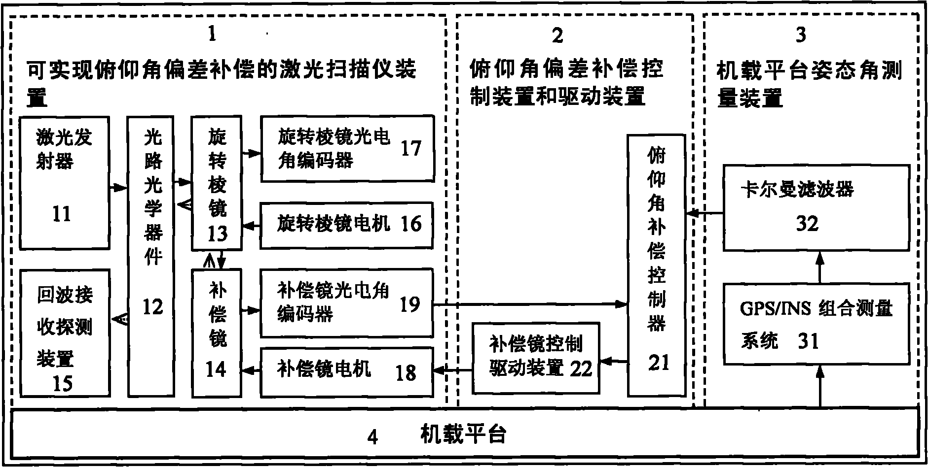
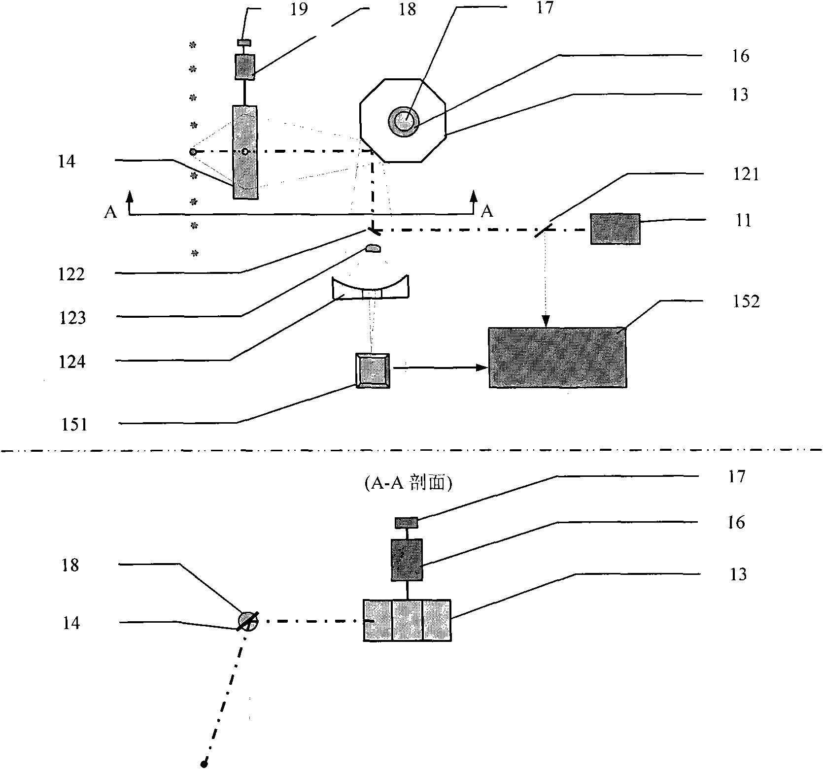
[0020] figure 1It is a schematic diagram of the overall structure of a method and device for real-time compensation of pitch angle deviation of airborne laser radar. During actual flight, due to the interference of various internal and external factors, the airborne platform (4) cannot maintain an ideal uniform linear motion state and a constant attitude angle (the ideal roll angle and pitch angle are zero, and the yaw angle is a constant), resulting in attitude angle deviation (including roll angle, pitch angle and yaw angle deviation). The attitude angle deviation of the airborne platform (4) is measured by the GPS / INS combination device (31), and the measurement data passes through the Kalman filter (32) to obtain a high-precision pitch angle deviation, which is sent to the Described pitch angle compensation controller (21). In...


PUM


Abstract

The invention discloses an airborne laser radar pitch angle deviation real-time compensation method and an airborne laser radar pitch angle deviation real-time compensation device. The device comprises a laser scanner device capable of realizing pitch angle deviation compensation, a pitch angle compensation controller and driving device, a GPS / INS combined measurement device, wherein the laser scanner device capable of realizing the pitch angle deviation compensation comprises a laser scanning transmitting and receiving system, a scanning prism, a compensation mirror, a photoelectric axial angle encoder and a compensation mirror motor; the GPS / INS combined measurement device acquires the attitude angle (pitch angle, rolling angle and yaw angle) deviation of a airborne platform and provides the acquired attitude angle deviation to the pitch angle compensation controller and driving device; and the pitch angle compensation controller and driving device controls the motor of the compensation mirror by using a compensation signal, receives a feedback signal from the compensation mirror photoelectric angle encoder, completes the closed-loop control of the pitch angle deviation compensation mirror and realizes the real-time high-accuracy compensation of the pitch angle deviation of an airborne laser radar.

Description

technical field [0001] The invention relates to a method and a device for improving the three-dimensional imaging resolution of a point-scanning airborne laser radar, in particular to a method and a device for real-time compensation of the pitch angle deviation of the airborne laser radar. Background technique [0002] Airborne lidar is a terrain mapping technology based on the principle of laser ranging, which integrates aircraft platforms, laser scanners, differential global positioning system DGPS (Differential Global Positioning System), inertial navigation system INS (Initial Navigation System) and computer data acquisition and processing system, etc. [0003] The working principle of the existing laser radar is as follows: the laser emits high-frequency laser pulses according to a certain pulse repetition frequency. After one laser pulse passes through the beam splitter, a part of the laser light directly reaches the distance counter to obtain the emission time of the ...

Claims


Application Information

Patent Timeline
IPC IPC(8): G01S7/481G01S17/89
Inventor 徐立军王建军李小路郜蕾
Owner BEIHANG UNIV
Learn More