
Radiation measuring device of light-gathering heat collection pipe and scanning analysis method thereof

A technology of measurement device and analysis method, which is applied in the field of solar heat collection, can solve the problems of difficult high-magnification focused irradiation of photodiode arrays, inability to measure optical power spectral density, single measurement parameters, etc., and achieve convenient and accurate two-dimensional scanning position control Effect

Inactive Publication Date: 2010-10-27
NORTH CHINA ELECTRIC POWER UNIV (BAODING)
View PDF2 Cites 15 Cited by
  • Summary
  • Abstract
  • Description
  • Claims
  • Application Information

AI Technical Summary

Problems solved by technology

[0003] The above two methods have single measurement parameters, can only obtain the distribution of the radiation power density, but cannot obtain the information of the distribution of the optical power spectral density, and the photodiode array is difficult to directly withstand high-magnification focused radiation, and it is necessary to configure light attenuation components, which increases the measurement error
Since the incident angle of light on the heat collecting tube in the trough solar focusing system changes constantly, the camera-Lambert target measurement method needs to check and compensate the data, and it is also impossible to measure the optical power spectral density

Method used


Image

  • Radiation measuring device of light-gathering heat collection pipe and scanning analysis method thereof
  • Radiation measuring device of light-gathering heat collection pipe and scanning analysis method thereof
  • Radiation measuring device of light-gathering heat collection pipe and scanning analysis method thereof

Examples


Embodiment Construction

[0034]The device structure and scanning measurement method of the present invention will be further described below in conjunction with the accompanying drawings.

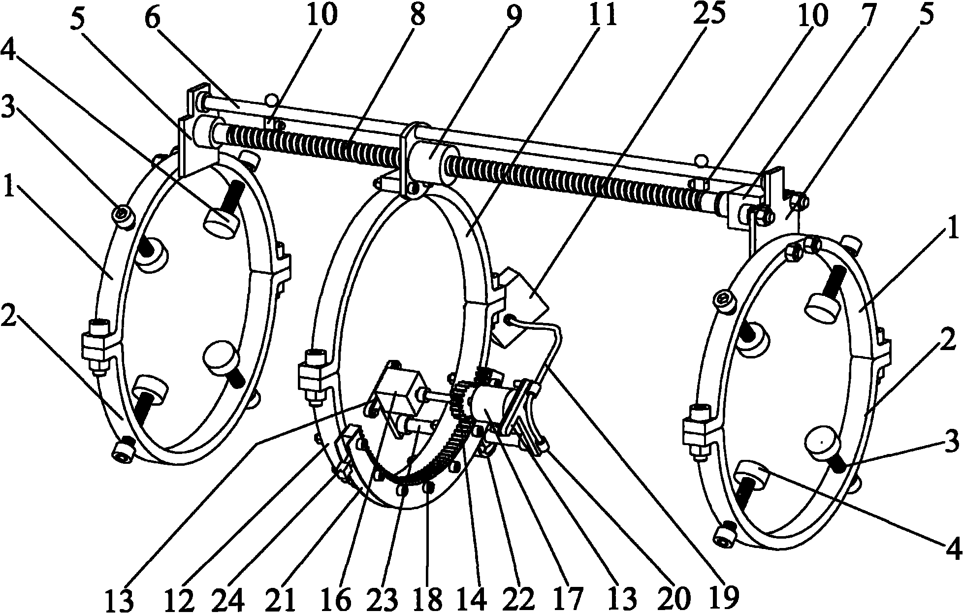
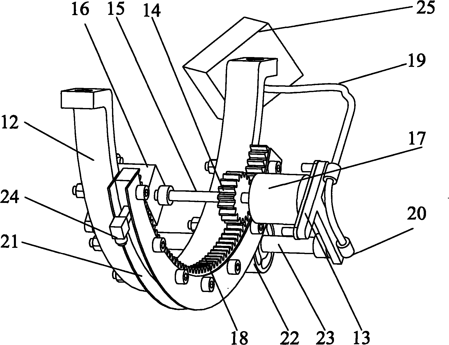
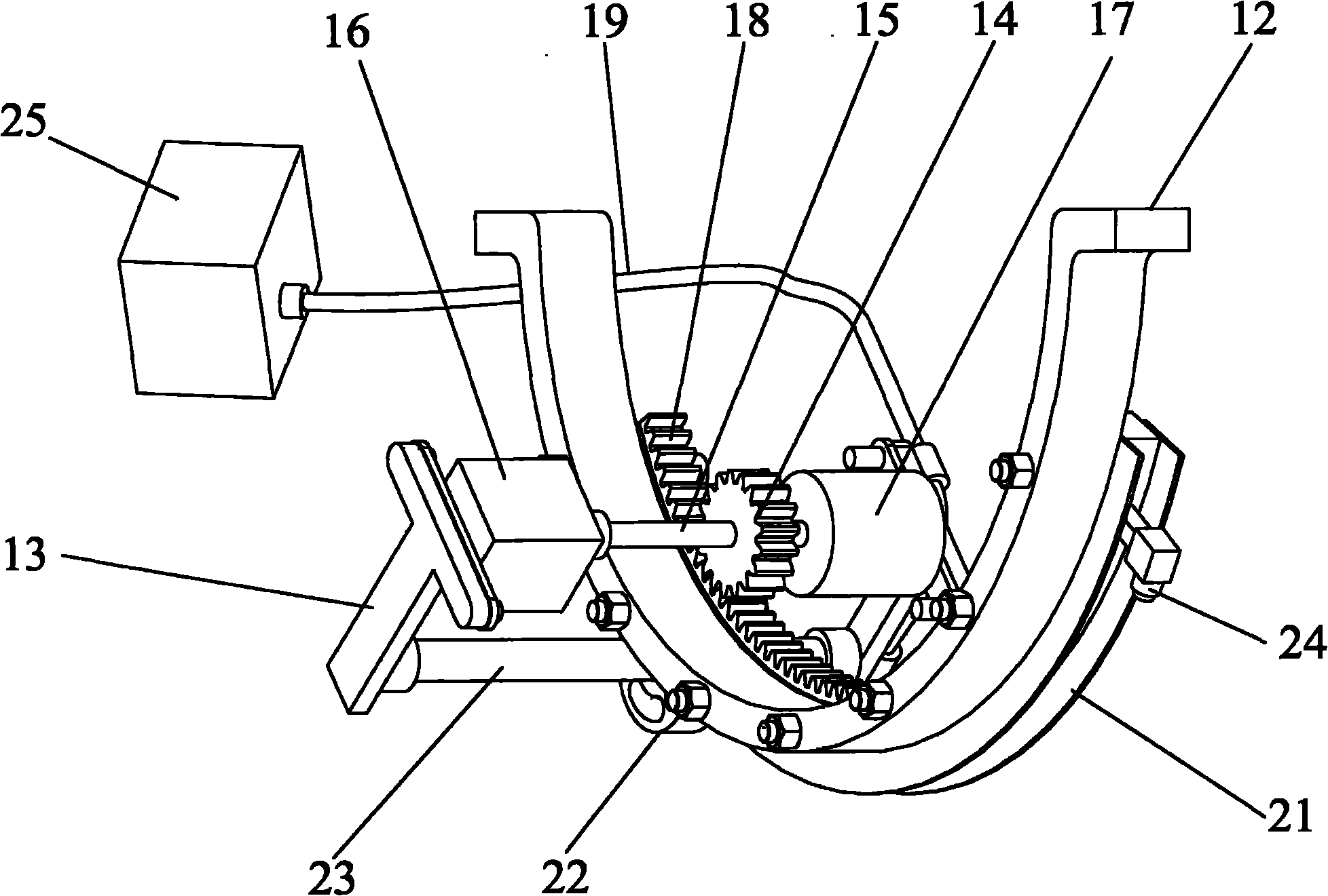
[0035] figure 1 It is a schematic diagram of the device structure of the present invention. The radiation measurement device of the concentrating heat collecting tube is composed of a heat collecting tube ferrule, an axial scanning driver, a circumferential scanner and a spectroradiometer. The heat collecting tube ferrule includes two ferrule units. Connected to the lower end of the guide rail bracket 5, the lower ferrule 2 and the upper ferrule 1 are connected by bolts to form a ring-shaped ferrule unit. The upper ferrule 1 and the lower ferrule 2 are each provided with 2 threaded holes, 4 The threaded holes are equally spaced on the ring-shaped ferrule unit. The thimble 3 is matched with the upper ferrule 1 or the lower ferrule 2 through the thread pair and the length in the ferrule is adjusted through the threa...


PUM

PropertyMeasurementUnit
Arc angleaaaaaaaaaa

Abstract

The invention belongs to the field of solar heat collection, in particular relates to a radiation measuring device of light-gathering heat collection pipe and a scanning analysis method thereof. The radiation measuring device of light-gathering heat collection pipe comprises a heat collection pipe sleeve, an axial scanning driver, wherein a circumferential scanner and a spectral radiometer, the device is fixed on the heat collection pipe to be measured to form a heat collection pipe assembly, the heat collection pipe assembly is arranged on the focal line of a parabolic groove face reflector, the axial scanning driver realizes the axial movement of the circumferential scanner, the circumferential scanner realizes the circumferential scanning movement of optical fiber, and the optical fiber transmits the received radiation energy to the spectral radiometer, so that fine measurement of radiation energy flow at the surface of the heat collection pope is realized; the scanning analysis method uses optical fiber to collect and transmit the focus radiation energy at the wall surface of the heat collection pipe point by point, uses the spectral radiometer to measure the optical parameters, and optically detects the parameters of the radiation energy flow at the wall surface of the heat collection pipe including light intensity, optical power spectral density, color temperature, and the like. The invention is applied to solar thermal power generation requiring high power condensation.

Description

technical field [0001] The invention belongs to the field of solar heat collection, and in particular relates to a radiation measurement device of a light concentrating heat collection tube and a scanning analysis method thereof. Background technique [0002] The solar energy flow density is low, and the ground radiation intensity generally does not exceed 1kw / m 2 , the energy taste is low, and it is difficult to develop and utilize high value. Using concentrating technology to focus sunlight, high-density energy flow can be obtained, and the efficiency of photothermal and photoelectric conversion can be greatly improved. Solar focusing modes include trough, tower, dish and other types, which can achieve focusing ratios of tens to hundreds and thousands of times respectively. Due to factors such as tracking error, optical mirror deformation, and sun angle of view, the energy flux density and optical power spectral density of the focused spot area are inhomogeneous and dyna...

Claims


Application Information

Patent Timeline
IPC IPC(8): G01J1/04G01J3/28H02K7/10F24J2/46
CPCY02E10/40
Inventor 宋记锋杨勇平侯宏娟张民幸
Owner NORTH CHINA ELECTRIC POWER UNIV (BAODING)
Learn More