Flowing friction welding method and tool thereof

A technology of flow friction and welding method, which is applied in the direction of welding equipment, manufacturing tools, non-electric welding equipment, etc., which can solve the problems of lap interface distortion and incomplete penetration, and achieve the effect of material performance optimization

Inactive Publication Date: 2010-11-03
BEIJING FSW TECH
View PDF1 Cites 14 Cited by
  • Summary
  • Abstract
  • Description
  • Claims
  • Application Information

AI Technical Summary

Problems solved by technology

During the friction stir welding process, due to the stirring effect of the stirring pin, the "S line" defect, the distortion of the lap joint interface, and the incomplete penetration defect are prone to appear in the joint

Method used


Image

  • Flowing friction welding method and tool thereof
  • Flowing friction welding method and tool thereof
  • Flowing friction welding method and tool thereof

Examples


Embodiment 1

[0032] Embodiment 1 Flow friction spot welding (Friction Flow Spot Welding, referred to as FFSW)

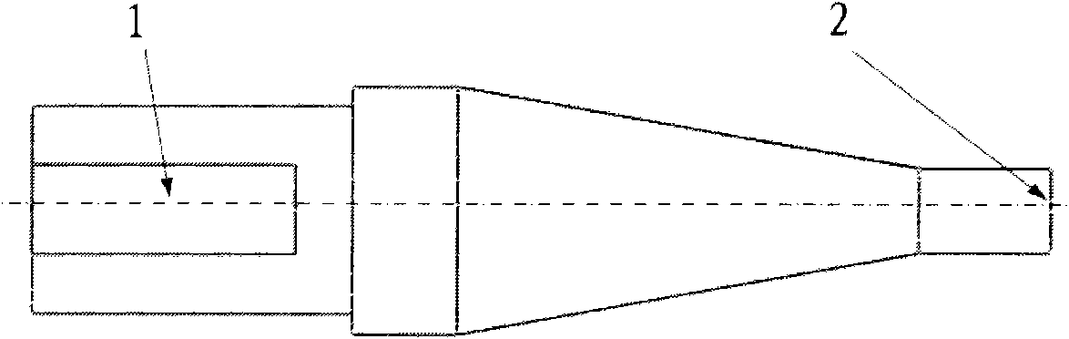
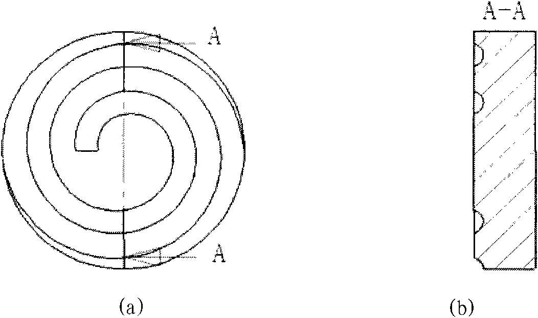
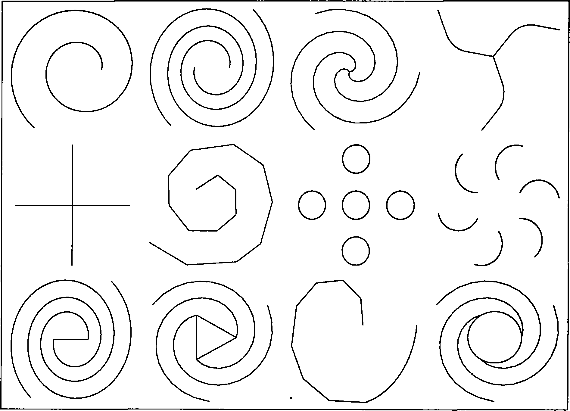
[0033] Spot welding 2mm thick 2524-T3 aluminum alloy, the diameter of the flow friction head is Φ10mm, the macroscopic shape of the end surface groove is helical, 2 helical lines, the cross-sectional shape of the groove is semicircular, the groove depth is 0.3mm, and the grooves everywhere Same deep.

[0034] The flow friction spot welding method is to place the flow friction head on the welding equipment and rotate it at 400 rpm. The axis of the flow friction tool contacts the surface of the workpiece at an angle of 0° with the surface of the workpiece to be welded. After contact, the flow friction The tool applies a normal pressure of 5KN to the workpiece. After the flow friction tool maintains the normal pressure, rotates continuously and stays on the workpiece for 5 seconds, the flow friction tool moves upward, and the end surface of the flow friction tool leaves the upper su...

Embodiment 2

[0035] Embodiment two flow friction spot welding

[0036]Spot welding 3mm thick 6082-T6 aluminum alloy, the diameter of the flow friction head is Φ15mm, the macroscopic shape of the end surface groove is spiral, with 3 helical lines, the cross-sectional shape of the groove is semicircular, and the depth of the groove is the groove opening and the groove tail Between 0.1 ~ 2mm linear gradient. The inclination angle of the flow friction head axis is 3°, the rotation speed is 2400 rpm, the normal force is 30KN, and the residence time is 30 seconds. Finally, a defect-free 3mm thick 6082 aluminum alloy flow friction spot welded joint was obtained.

Embodiment 3

[0037] Embodiment three flow friction butt welding

[0038] Flow friction butt welding of 5mm thick 6082-T6 aluminum alloy, using a flow friction head with a diameter of Φ20mm, the macroscopic shape of the end surface groove is a spiral, four helical lines, the groove depth is 2mm, and the cross-sectional shape of the groove is an inverted triangle.

[0039] The flow friction butt welding method is to place the flow friction tool on the welding equipment and rotate it at 2000 rpm. The axis of the flow friction tool contacts the surface of the workpiece at an angle of 5° with the surface of the workpiece to be welded. After contact, the flow friction The tool applies a normal pressure of 100KN to the workpiece. After the flow friction tool maintains the normal pressure, rotates continuously and stays on the workpiece for 6 seconds, it moves at a speed of 100mm / min in a direction parallel to the surface of the workpiece. After welding, the flow friction tool moves upward Move th...


PUM


Abstract

The invention belongs to a welding technique, in particular to a flowing friction welding method suitable for connecting and processing homogeneous or heterogeneous thermoplastic materials and repairing workpiece defects and a tool thereof. The welding method comprises the following steps of: placing a flowing friction tool on welding equipment and rotating the flowing friction tool by 40-4000 turns/minute; contacting the axis of the flowing friction tool with the surface of a welded workpiece by the included angle of 0-15 degrees, and then applying the normal pressure of 0.1-100 kN to the workpiece by using the flowing friction tool; making the flowing friction tool keep the normal pressure and continuous rotation and remain 2-30 seconds on the workpiece, and then welding. The end surface of a friction head of the flowing friction tool used in the invention is provided with a spiral or radial tank. Because the flowing friction tool does not extend into the workpiece, no keyholes in stirring friction welding exist in the invention. The invention can be widely applied in the fields of spot welding, overlapping joint, abutting joint, defect repairing, material processing and the like.

Description

technical field [0001] The invention belongs to the welding technology, and relates to a flow friction welding method suitable for the connection of the same or different thermoplastic materials (such as butt joint, lap joint, spot welding, etc.), and also suitable for the grain refinement processing of materials and the repair of workpiece defects and its tools. Background technique [0002] Friction Stir Welding (FSW for short, US Patent No. 5,460,317) invented by The Welding Institute in the United Kingdom is a solid phase joining technology. The tool used in friction stir welding is a stirring head, and the main structure of the stirring head includes a clamping handle (the connection part between the stirring head and the power system), a shaft shoulder and a stirring needle. During the friction stir welding process, the stirring head rotates and applies an upsetting force in the axial direction of the stirring head to the workpiece. The stirring needle first touches t...

Claims


Application Information

Patent Timeline
Patent Type & Authority Applications(China)
IPC IPC(8): B23K20/12B23K20/26
Inventor 王卫兵李光栾国红董春林
Owner BEIJING FSW TECH
Why Eureka
Try Eureka