

Diamond wire saw
A diamond wire saw and diamond technology, applied in metal processing equipment, stone processing equipment, grinding machines, etc., can solve the problems that the service life of the diamond wire saw cannot be improved, and the diamond is easy to fall off, so as to achieve normal and durable use, high welding strength, The effect of improving the service life
- Summary
- Abstract
- Description
- Claims
- Application Information
AI Technical Summary
Problems solved by technology
Method used
Image

Examples
Embodiment 1
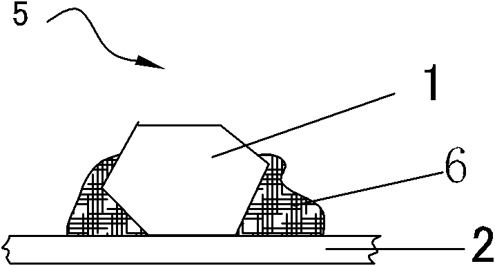
[0054] Take a large steel sheet with a thickness of 0.1 mm, cut it into several small steel sheets with a length of 3.14 mm and a width of 2 mm, and braze or electroplate diamond particles 1 on the small steel sheets to obtain a diamond substrate 5 . Such as Figure 1a As shown in , the diamond substrate 5 is composed of diamond particles 1 and small pieces of steel sheet 2 .
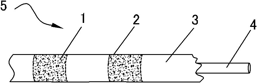
[0055] Select a multi-strand alloy steel wire rope 4 with a diameter of 1mm, coat the surface with epoxy resin after degreasing treatment, then coat the bottom surface of the prepared diamond substrate 5 (without diamond surface) with epoxy resin, and curl it into a It is cylindrical and bonded to the wire rope 4 at intervals of 5 mm.
[0056] After the glue is cured, evenly coat a layer of two-component polyurethane adhesive (flexible) on the alloy steel wire rope 4 bonded with the diamond substrate 5, and the polyurethane adhesive buries the steel wire rope 4 and the diamond substrate 5 except cutting...
Embodiment 2
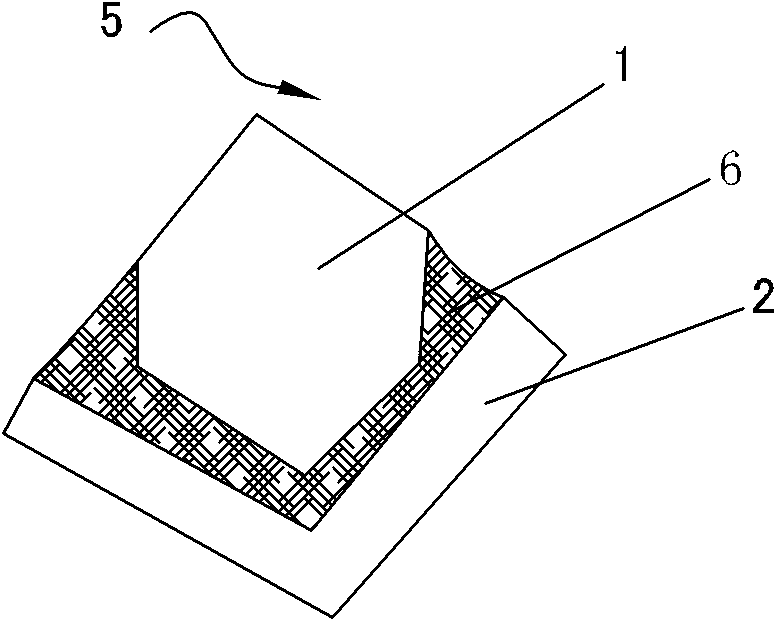
[0060] Such as Figure 4 As shown in , take a large steel sheet with a thickness of 0.1 mm, cut it into several irregularly shaped small steel sheets with a length of 3 mm and a width of 0.8 mm, and braze or electroplate diamond particles 1 on the small steel sheets , obtain a diamond substrate 5, the diamond substrate 5 is composed of diamond particles 1 and a small piece of steel sheet 2.
[0061] Select a steel wire 4 with a square (side length of 0.8 mm) cross-section, and then spot-weld the prepared diamond substrate 5 to one of the steel wires 4 at intervals of 5 mm. on flat surface. After the welding is completed, the square steel wire rope welded with the diamond substrate 5 is twisted into a spiral shape. At this time, the diamond substrate 5 is distributed in each direction of the square steel wire rope.
[0062] Get the adhesive (flexible), which includes 89% polyurethane adhesive, 10% diamond powder (600 mesh) and 1% polyurethane fine fiber by weight percentage i...
Embodiment 3
[0066] The prepared length is 3mm, the width is 2mm, and the diamond substrate 5 with at least one diamond particle is brazed or electroplated for use. The diamond substrate 5 is made up of diamond particles 1 and small pieces of steel sheet 2, such as Figure 1a shown in .
[0067] Choose a multi-strand alloy steel wire rope 4 with a diameter of 1 mm. After surface degreasing treatment, the bottom surface of the prepared diamond substrate 5 (without diamond surface) is directly welded to each direction on the gold steel wire rope. Every two adjacent diamond substrates The interval between the sheets 5 is about 6 mm.
[0068] On the alloy steel wire rope 4 that is bonded with diamond substrate 5, evenly coat one deck of two-component polyurethane adhesive (flexibility), the polyurethane adhesive buryes the area other than the cutting surface on the steel wire rope 4 and the diamond substrate 5, After the above adhesive is completely cured, a polyurethane layer 3 is formed. In...
PUM
| Property | Measurement | Unit |
|---|---|---|
| Diameter | aaaaa | aaaaa |
| Granularity | aaaaa | aaaaa |
| Diameter | aaaaa | aaaaa |
Abstract
Description
Claims
Application Information