Bridge frame dedicated for nuclear power and length connecting component thereof

A technology for connecting components and bridges, applied in the direction of pipes/pipe joints/pipes, pipe supports, mechanical equipment, etc., can solve the problems of reducing the strength and bearing capacity of the bridge, the connection between the edge of the ladder and the ladder is not strong enough, and the connection cannot be tightly combined, etc. , to achieve the effect of being conducive to heat dissipation, improving service life and safety performance, and convenient processing

Inactive Publication Date: 2010-11-10
JIANGSU HUAQIANG ELECTRIC EQUIP
View PDF7 Cites 1 Cited by
  • Summary
  • Abstract
  • Description
  • Claims
  • Application Information

AI Technical Summary

Problems solved by technology

The connecting members of the bridge length in the prior art are usually L-shaped members. The vertical plates are connected to the sides of the ladder sides through fasteners, and the horizontal plates are wrapped on the bottom surface of the bridge frame. Since the connecting members and the sides of the ladder sides are flat plates, this Not only is the load capacity limited, the strength is low, and the shock resistance is poor, but the connection between the ladder side and the ladder shank is not strong enough; in addition, because the connection between the ladder side and the ladder shank is connected through three horizontal holes and three vertical holes, the connection cannot be tightly combined. Not strong enough, the appearance is not beautiful, and because the punched holes are concentrated on the center line of the ladder side, the strength of the whole ladder side is not enough; thus, the strength and bearing capacity of the bridge frame are greatly reduced

Method used


Image

  • Bridge frame dedicated for nuclear power and length connecting component thereof
  • Bridge frame dedicated for nuclear power and length connecting component thereof
  • Bridge frame dedicated for nuclear power and length connecting component thereof

Examples


Embodiment Construction

[0018] The present invention will be further described below in conjunction with accompanying drawing.

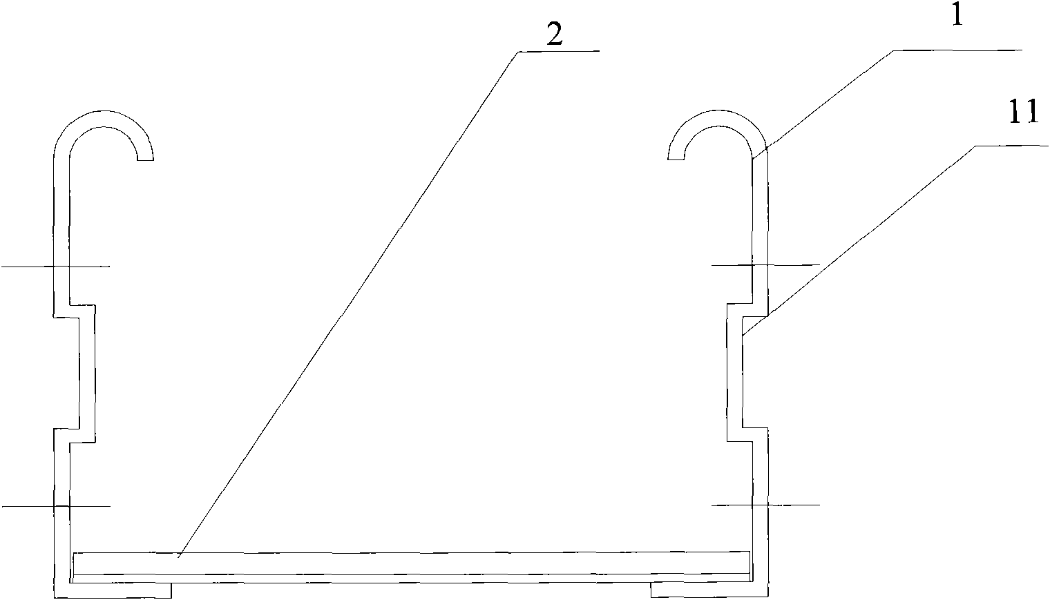
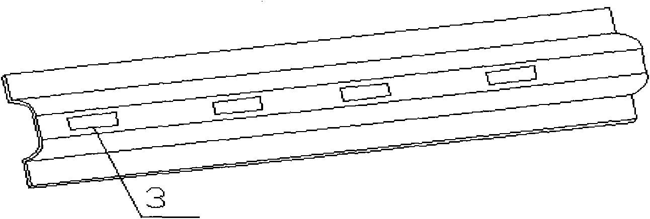
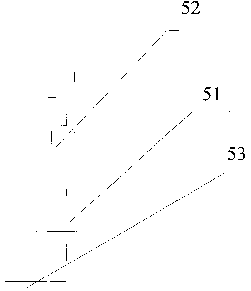
[0019] As shown in the figure, in order to solve the above technical problems, the present invention provides a special bridge for nuclear power, including a ladder side 1 and a ladder bar 2, and the ladder side 1 is fixedly connected to the two ends of the ladder bar 2 by welding or other means. In the shape of a groove, the side of the step edge 1 is provided with a longitudinal groove 11, the shape of the longitudinal groove 11 is not limited, it can be a square groove, or an arc-shaped groove, and the longitudinal groove The number of 11 is not limited, can be designed according to actual needs, can be one, also can be multiple. Since the side of the ladder side 1 is provided with a groove 11, the ladder side of this shape has the characteristics of strong load capacity and high seismic strength, thereby improving the overall strength and strong bearing capacity of the ...


PUM


Abstract

The invention provides a bridge frame dedicated for nuclear power and a length connecting component thereof. The bridge frame dedicated for nuclear power comprises ladder sides and a ladder, wherein the ladder sides and the ladder are connected into the whole body by the connecting components; and the lateral surfaces of the ladder sides are provided with longitudinal grooves. Because the lateral surfaces of the ladder sides are provided with the longitudinal grooves, the shaped ladder sides have the characteristics of strong load-carrying capacity and high shock strength so as to improve the integral strength and bearing capability of the bridge frame and make the protection grade of the bridge frame reach IP66 to further greatly improve the safety performance of the bridge frame. Moreover, the invention only improves the shape of the ladder sides of the bridge frame, thus, the processing is convenient and the structure is simple.

Description

technical field [0001] The invention relates to a bridge frame and a bridge length connecting member used in conjunction with the bridge frame, belonging to the technical field of cable laying equipment. Background technique [0002] Cable bridges are widely used in petroleum, chemical, electric power, light industry, telecommunications and other industries, mainly used for the laying of overhead power cables, control cables, lighting lines, and telecommunication cables, which require high strength and carrying capacity of the bridge. The bridge frame includes ladder sides and ladder knuckles, and the ladder sides and the ladder knuckles are fixed as a whole. Usually, the cross-sectional shape of the ladder side profiles of the cable bridge is changed to improve the strength, bearing capacity and bending resistance of the bridge frame. [0003] The ladder side of the traditional cable bridge is made of single-layer steel plate pressing, and the section of the bridge ladder s...

Claims


Application Information

Patent Timeline
Patent Type & Authority Applications(China)
IPC IPC(8): F16L3/06
Inventor 陈廷国
Owner JIANGSU HUAQIANG ELECTRIC EQUIP
Why Eureka
Try Eureka