
Laser power detection device and detection method thereof

A technology for optical power detectors and detection devices, applied in measuring devices, photometry, optical radiation measurement, etc., can solve the problem of not being able to measure the number of laser pulses at the same time, continuous working time not being too long, and damage to the carbon bucket detection surface and other problems, to achieve the effect of convenient and fast measurement, stable work and simplified structure

Inactive Publication Date: 2010-11-10
安徽中科转化医学研发中心有限公司
View PDF0 Cites 10 Cited by
  • Summary
  • Abstract
  • Description
  • Claims
  • Application Information

AI Technical Summary

Problems solved by technology

Although the commonly used power meter has a nominal measurement range of several hundred watts or even kilowatts, there are insurmountable defects in this kind of power meter. First, the carbon bucket is easily damaged when measuring the laser power. , so that the measurement is no longer accurate, so the continuous working time should not be too long. The reason is that the carbon bucket needs to fully absorb the laser to perform effective detection, and the continuous irradiation of an excessively high-power laser can easily damage the detection surface of the carbon bucket. ; Secondly, it needs to be accompanied by a bulky refrigeration equipment to effectively cool the carbon bucket, which not only makes it too large in size, but also inconvenient to use, and the cost of measurement is also high; again, only the power of the laser can be measured, and the The number of laser pulses cannot be measured simultaneously

Method used


Image

  • Laser power detection device and detection method thereof
  • Laser power detection device and detection method thereof
  • Laser power detection device and detection method thereof

Examples


Embodiment Construction

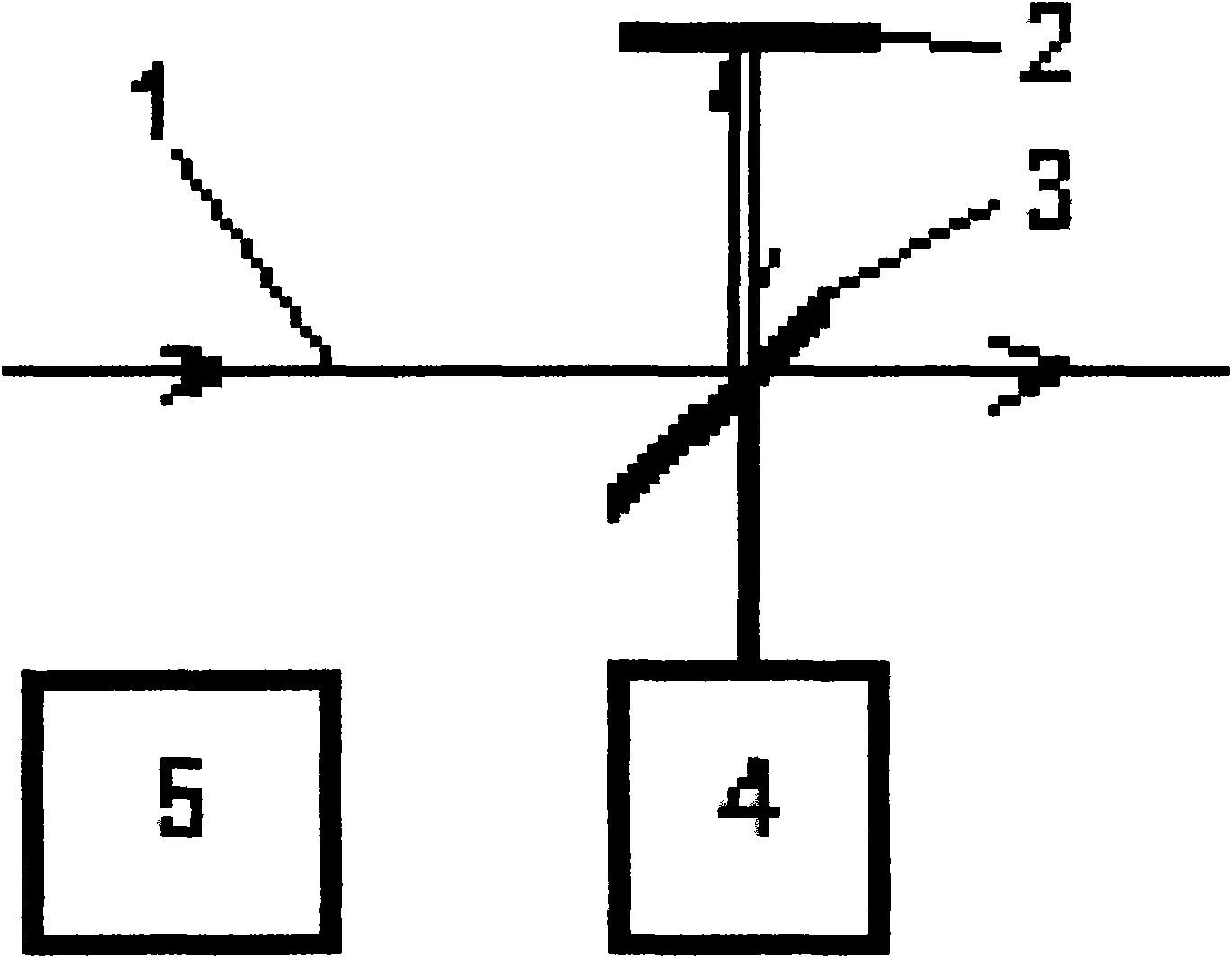
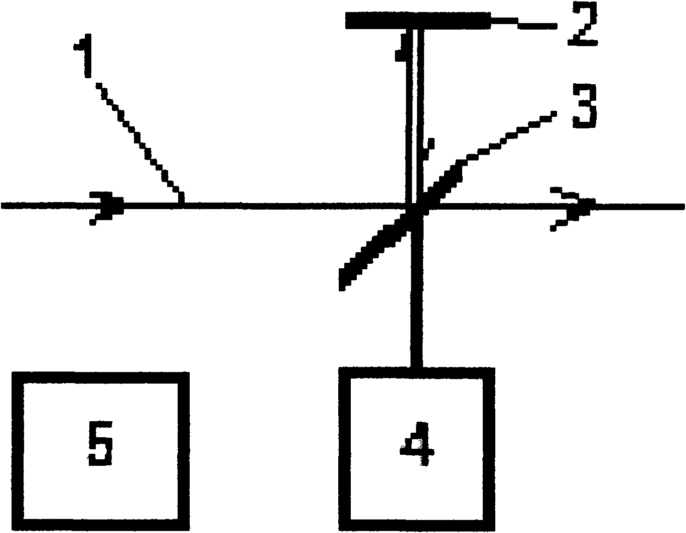
[0018] see figure 1 An attenuator composed of two white sapphire glass lenses is interposed between the laser light 1 to be measured and the light detection component 4 . The first white sapphire glass lens 3 in the attenuator is located on the optical path of the laser light 1 to be measured, and is set at an angle of 45 degrees to the optical path of the laser light 1 to be measured, and the second white sapphire glass lens 2 is located on the optical path of the first white sapphire glass lens 3 The reflected optical path, and its mirror surface is parallel to the optical path of the laser to be measured 1; wherein, the thickness of the first white sapphire glass lens 3 and the second white sapphire glass lens 2 are both 3mm. The photodetector 4 is located on the reflected light path of the second white sapphire glass lens 2 on the back of the first white sapphire glass lens 3 . Optical detection part 4 is made up of optical power detector and optical pulse detector, and t...


PUM

PropertyMeasurementUnit
Thicknessaaaaaaaaaa

Abstract

The invention discloses a laser power detection device and a detection method thereof. The device is an attenuator formed by arranging two white stone glass mirrors between a laser (1) to be detected and an optical detector (4), wherein the first white stone glass mirror (3) forms a 45 DEG angle with the light path of the laser (1) to be detected and is arranged above the light path, the second white stone glass mirror (2) is located on the reflecting light path of the first mirror, and the mirror surface of the second white stone glass mirror (2) is parallel to the light path of the laser (1) to be detected; the optical detector (4) is located on the reflecting light path of the second mirror on the back surface of the first mirror, and all the output ends of the optical detector (4) comprising an optical power detector and an optical pulse detector are electrically connected with the input end of a data processing unit (5). The method comprises the following steps of: firstly, respectively processing signals output by the optical power detector and the optical pulse detector; and then, sending the obtained power value and the obtained pulse number to a display. The device has simple structure, small size and easy use, can be used for continuously measuring the laser power and the pulse number, and can also be used for measuring a high-power laser.

Description

technical field [0001] The invention relates to a laser detection device and a detection method, in particular to a laser power detection device and a detection method. Background technique [0002] With the development of the laser industry, the application of high-power lasers in welding and cutting is becoming more and more popular. However, it is more and more difficult to measure high-power lasers with hundreds of watts or even several kilowatts. Most of the existing equipment for measuring high-power lasers is a power meter, and the receiving part is a power probe, that is, a carbon bucket, which is composed of a conical light-absorbing material and a copper or aluminum heat-conducting substrate; the power The working principle of the meter is to convert the laser light into heat through the carbon bucket, and then convert the heat into an electrical signal that can be used for data analysis. Although the commonly used power meter has a nominal measurement range of se...

Claims


Application Information

Patent Timeline
IPC IPC(8): G01J1/00G01J1/04G01J11/00
Inventor 吴先友张飞军付毅宾江海河
Owner 安徽中科转化医学研发中心有限公司
Learn More