
High-efficiency annealing furnace capable of avoiding bonding of cold-rolled strip steel and operating method thereof

A cold-rolled strip, high-efficiency technology, applied in the field of heat treatment, can solve the problems of reducing the operability and bulky volume of large-diameter cold-rolled steel coils, reducing ineffective emissions, improving production efficiency, and increasing heating and cooling rates. Effect

Inactive Publication Date: 2010-11-17
SHANDONG IRON & STEEL CO LTD
View PDF5 Cites 15 Cited by
  • Summary
  • Abstract
  • Description
  • Claims
  • Application Information

AI Technical Summary

Problems solved by technology

However, the device is bulky, which reduces the operability of large-diameter cold-rolled steel coils in the annealing furnace

Method used


Image

  • High-efficiency annealing furnace capable of avoiding bonding of cold-rolled strip steel and operating method thereof
  • High-efficiency annealing furnace capable of avoiding bonding of cold-rolled strip steel and operating method thereof
  • High-efficiency annealing furnace capable of avoiding bonding of cold-rolled strip steel and operating method thereof

Examples


Embodiment 1

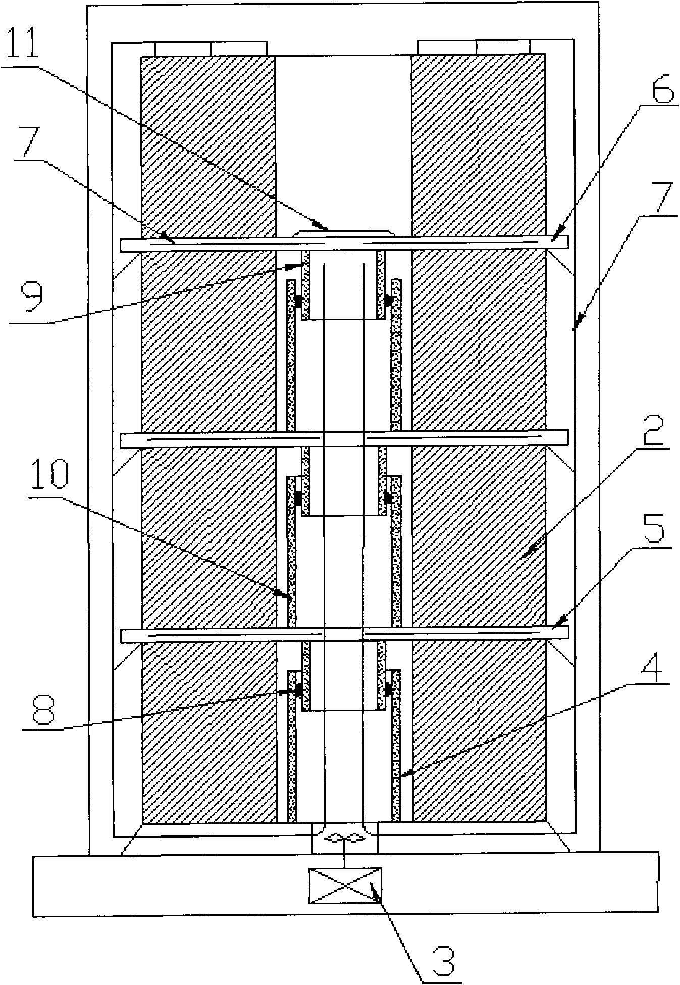
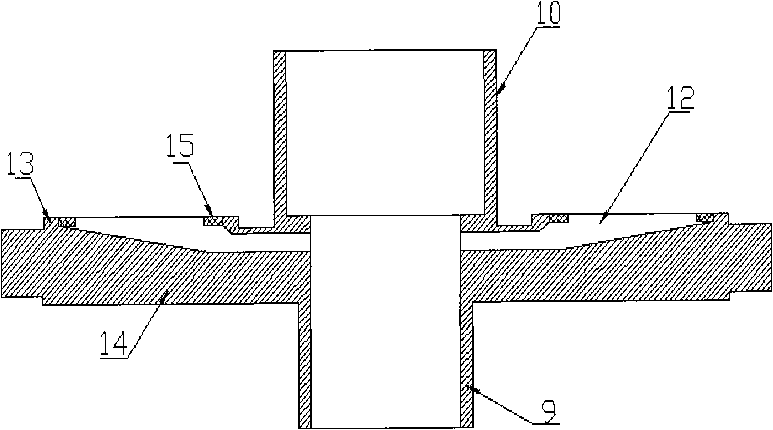
[0044] Such as figure 2 As shown, the four rings of the independent guide pipe are covered with the air outlet of the blower reserved on the hearth, and the length of the independent guide pipe is 100mm smaller than the minimum width of the cold-rolled steel strip that the production line can produce; Stacked on the hearth, so that the independent guide tube is located at the core of the first steel coil; then the guide plate 5 with the upper and lower guide tubes is placed on the first coil, and the upper half of the guide plate There are 30 radial air guide passages (12) centered on the center of the deflector plate in the layer. Wherein the external diameter of lower guide tube 9 is 5mm less than the inner diameter of independent guide tube 4, and the height is 100mm smaller, and the inner and outer diameters of upper guide tube 10 and independent guide tube 4 are the same, and the length is the same; the lower guide tube 9 Insert it into the independent draft tube 4 and ...

Embodiment 2

[0047] Such as figure 2 As shown, the four rings of the independent guide pipe are covered with the air outlet of the blower reserved on the hearth, and the length of the independent guide pipe is 50mm smaller than the minimum width of the cold-rolled steel strip that the production line can produce; Stacked on the hearth, so that the independent guide tube is located at the core of the first steel coil; then the guide plate 5 with the upper and lower guide tubes is placed on the first coil, and the upper half of the guide plate There are 36 radial air guide channels (12) centered on the center of the guide plate in the layer, wherein the outer diameter of the lower guide tube 9 is 2 mm smaller than the inner diameter of the independent guide tube 4, and the height is 50 mm smaller. The tube 10 has the same inner and outer diameters and the same length as the independent draft tube 4; the lower draft tube 9 is inserted into the independent draft tube 4 and sealed by a high-te...


PUM

PropertyMeasurementUnit
heightaaaaaaaaaa

Abstract

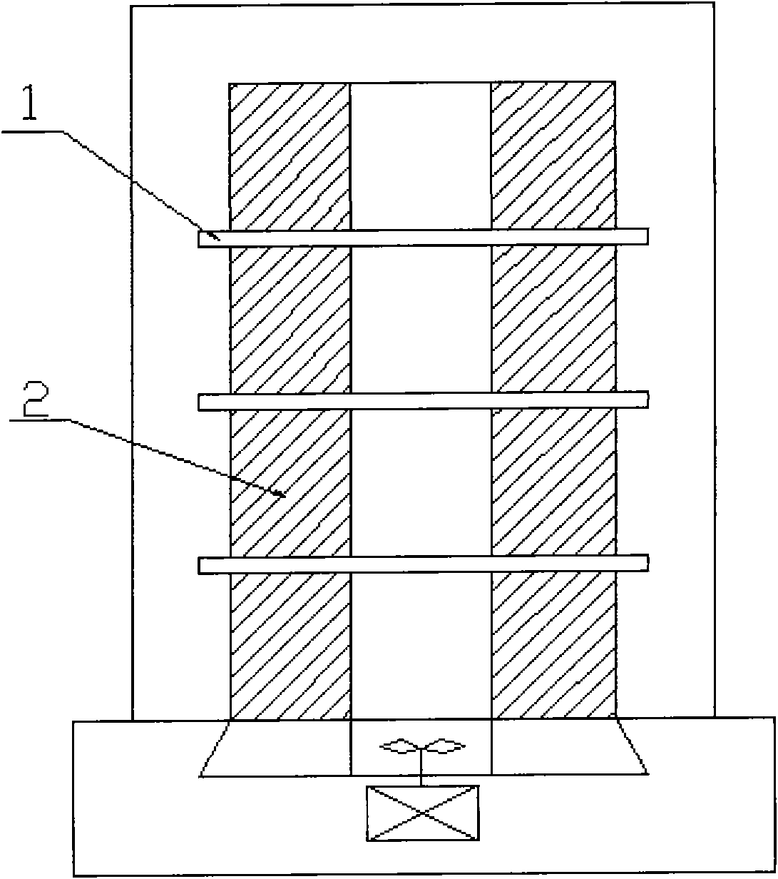
The invention discloses a high-efficiency annealing furnace capable of avoiding bonding of cold-rolled strip steel and an operating method thereof. The high-efficiency annealing furnace comprises a high power blower, a segment of independent flow guide tube, guide plates provided with upper flow guide tubes and lower flow guide tubes, a guide plate only provided with a lower flow guide tube, and a sealing ring. The annealing furnace is characterized in that the independent flow guide tube (4) is positioned at the core of a first cold-rolled steel coil on a furnace platform and sleeves a reserved air port of the blower on the furnace platform in a ring manner; the upper part of the independent flow guide tube (4) is connected with the lower flow guide tubes (9) of the guide plates (5) provided with the upper flow guide tubes and the lower flow guide tubes through the heat resistant sealing ring (8); the upper flow guide tubes and the lower flow guide tubes of the guide plates (5) provided with the upper flow guide tubes and the lower flow guide tubes are sequentially connected through the heat resistant sealing ring (8); and the guide plate (6) at the upmost end is only provided with the lower guide tube (9) and is arranged between two top steel coils. In the invention, the adopted heat cycle path is as follows: a heating mantle (a cooling mantle), an inner cover, protective gas in the furnace after completing warming (cooling) convection in the middle part, outer rings of the steel coils, and heat radiation of the cores of the steel coils, thus strengthening the convection effect in the middle part and reducing the phenomenon of unbalanced inner temperature and outer temperature.

Description

technical field [0001] The invention belongs to the technical field of heat treatment, and relates to a high-efficiency annealing furnace for avoiding the bonding of cold-rolled steel strips and a working method thereof. Background technique [0002] Bonding is the phenomenon of local welding between layers during tight coil annealing within a certain period of time under certain temperature and stress. During flat uncoiling, due to the influence of bonding, the strip steel no longer opens along the tangential direction of the steel coil, but produces a certain arc, and part of the bonding force becomes the force that makes the strip steel bend. When this component of the bonding force exceeds the yield limit of the strip, an arc bend perpendicular to the axial direction of the strip is formed. [0003] The existing bell-type annealing furnace usually adopts the single-stack tight-coil annealing method, and the steel coils are stacked one by one through the middle convectio...

Claims


Application Information

Patent Timeline
Patent Type & Authority Applications(China)
IPC IPC(8): C21D9/673
Inventor 张冠锋许荣昌刘洪银
Owner SHANDONG IRON & STEEL CO LTD
Learn More