Method and device for producing pressure oxygen by air separation

An air separation and pressure technology, applied in refrigeration and liquefaction, liquefaction, solidification and other directions, can solve the problems of high production cost and complex process, and achieve the effect of low equipment investment cost, improved separation capacity and reduced cost

Active Publication Date: 2010-11-17
四川空分设备(集团)有限责任公司
View PDF6 Cites 22 Cited by
  • Summary
  • Abstract
  • Description
  • Claims
  • Application Information

AI Technical Summary

Problems solved by technology

[0005] The purpose of the present invention is to overcome the disadvantages of high production cost and complicated process of the pressure oxygen production device and process in the prior art, and provid

Method used


Image

  • Method and device for producing pressure oxygen by air separation
  • Method and device for producing pressure oxygen by air separation
  • Method and device for producing pressure oxygen by air separation

Examples


Embodiment 1

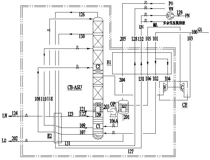
[0032] Embodiment 1: as figure 1 Shown, a kind of air separation produces the method for pressure oxygen, comprises the steps:

[0033] A. The clean compressed air 100 is divided into two paths. One path 103 is pressurized by the booster end of the expander CE and then enters the main heat exchanger E1 for cooling, and then enters the oxygen booster K2 to exchange heat with the pressure liquid oxygen to condense into a liquid state, and then Enter the rectification tower lower column C1 to participate in the rectification at a position of 3 to 7 theoretical plates from the bottom; the other path 101 enters the main heat exchanger E1 and cools down to 145K ~ 180K, and then divides into two parts, and one part 104 expands through the expansion end of the expander CE Then it is sent to the upper column C2 of the rectification tower to participate in the rectification; the other part 102 is sent to the lower tower C1 of the rectification tower, and after heat and mass transfer wit...

Embodiment 2

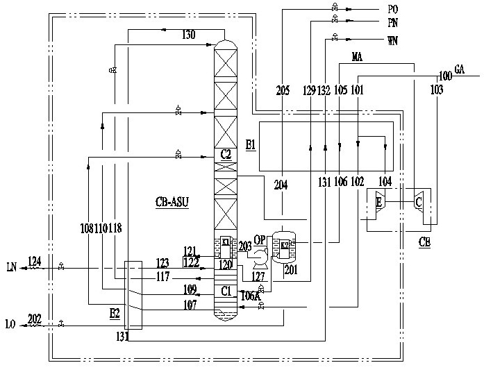
[0045] Embodiment 2: as figure 2 Shown, a kind of air separation produces the method for pressure oxygen, comprises the steps:

[0046] A. The clean compressed air 100 is divided into two paths. One path 103 is pressurized by the booster end of the expander CE and then enters the main heat exchanger E1 for cooling, and then enters the oxygen booster K2 to exchange heat with the pressure liquid oxygen to condense into a liquid state, and then Enter the rectification tower lower column C1 to participate in the rectification at a position of 3 to 7 theoretical plates from the bottom; the other path 101 enters the main heat exchanger E1 and cools down to 145K ~ 180K, and then divides into two parts, and one part 104 expands through the expansion end of the expander CE Then it is sent to the upper column C2 of the rectification tower to participate in the rectification; the other part 102 is sent to the lower tower C1 of the rectification tower, and after heat and mass transfer wi...


PUM


Abstract

The invention discloses a method for producing pressure oxygen by air separation. The compressed air is divided into two paths: one path of the compressed air is pressurized to enter a main heat exchanger for cooling, enter an oxygen pressurizer to exchange heat with pressure liquid oxygen to be condensed into a liquid state and enter a lower tower for rectification; and the other path of the compressed air enters the main heat exchanger for cooling and is divided into two parts, and one part of the air is expanded to be fed to an upper tower for rectification. The nitrogen obtained by the lower tower enters a condensing evaporator to be condensed into two parts, namely one part of the nitrogen serving as reflux returns to the lower tower and the other part of the nitrogen is subcooled through a subcooler and divided into two paths. One path of the nitrogen serving as liquid nitrogen is led out, and the other path of the nitrogen enters the top of the upper tower. Dirty liquid air extracted from the lower tower and the obtained liquid air are subcooled through the subcooler, enter the upper tower for rectification once again and pass through the condensing evaporator so as to form liquid oxygen. The liquid oxygen which is pressurized or subjected to liquid oxygen pump pressurization enters the oxygen pressurizer to be evaporated into pressure oxygen and reheated in the main heat exchanger for output. The method for producing the pressure oxygen has the advantages of optimized flow organization, low equipment input cost, and capacity of obviously reducing the energy consumption.

Description

technical field [0001] The invention relates to a gas separation device and method, in particular to a method and device for air separation to produce pressure oxygen. Background technique [0002] In the industrial production of glass, glass fiber, non-ferrous smelting, oxygen-enriched combustion, etc., a large amount of pressure oxygen is often required, the pressure is 0.7-2.2 barg, and a certain amount of pressure nitrogen is also required. For meeting this kind technological requirement, at present, mainly adopt following three kinds of methods: one, add the air booster compressor, compress in the oxygen; Two, improve the pressure of the air compressor in the air separation plant; compression. [0003] For method one, since the medium for heat exchange with pressure liquid oxygen needs to have sufficiently high pressure air, and the air for heat exchange with liquid oxygen in the existing air separation unit is usually not at high pressure, a separate air booster compr...

Claims


Application Information

Patent Timeline
IPC IPC(8): F25J3/04
Inventor 黄震宇
Owner 四川空分设备(集团)有限责任公司
Why Eureka
Try Eureka