
High-efficiency ammonia-method denitration process and device thereof

A technology of denitrification and ammonia method, which is applied in the field of non-coal contact ammonia denitrification process and equipment, can solve the problems of uneven temperature, low denitrification efficiency, and zero denitrification effect, and achieve the effect of improving the denitrification effect

Inactive Publication Date: 2013-03-13
东莞兆能环境科技有限公司 +1
View PDF0 Cites 0 Cited by
  • Summary
  • Abstract
  • Description
  • Claims
  • Application Information

AI Technical Summary

Problems solved by technology

In this process, the atomized ammonia liquid or urea solution at room temperature directly exchanges heat with the high-temperature flue gas in the high-temperature reaction zone, which will cause sudden cooling in the high-temperature reaction zone, and the temperature of each area in the high-temperature reaction zone will be uneven, resulting in Lead to low denitrification efficiency, the current general denitrification efficiency is only 30-50%, and the denitrification effect of the system is almost zero at 800 °C

Method used


Image

  • High-efficiency ammonia-method denitration process and device thereof
  • High-efficiency ammonia-method denitration process and device thereof
  • High-efficiency ammonia-method denitration process and device thereof

Examples


Embodiment

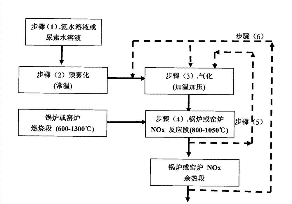
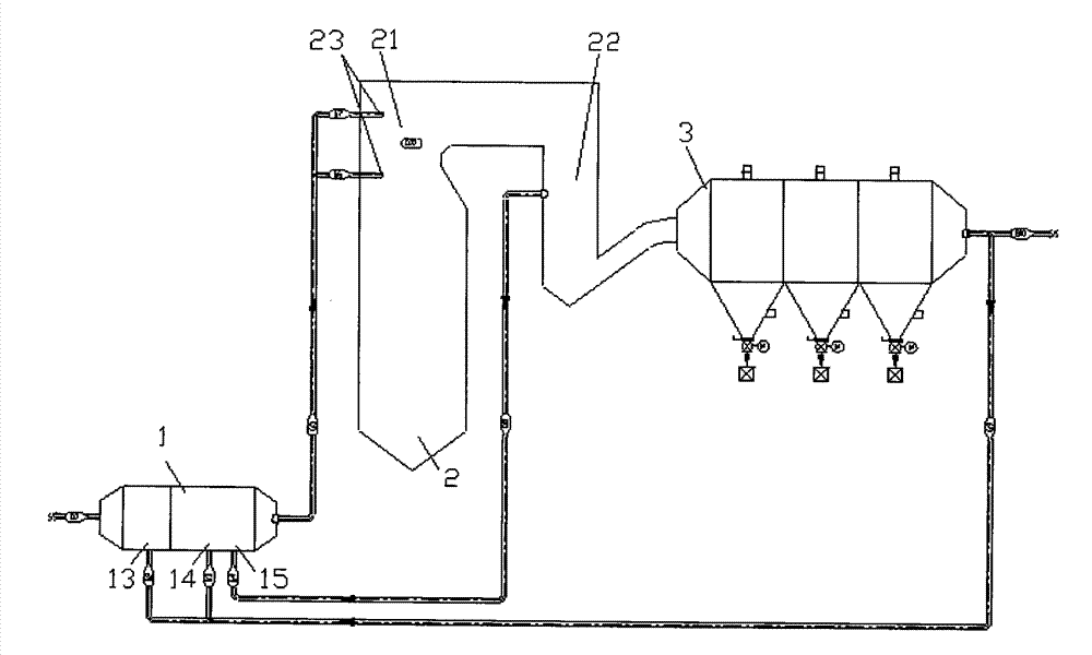
[0018] like Figure 1-3 Shown, technological process of the present invention is:

[0019] Step 1. Prepare ammonia solution or urea solution;

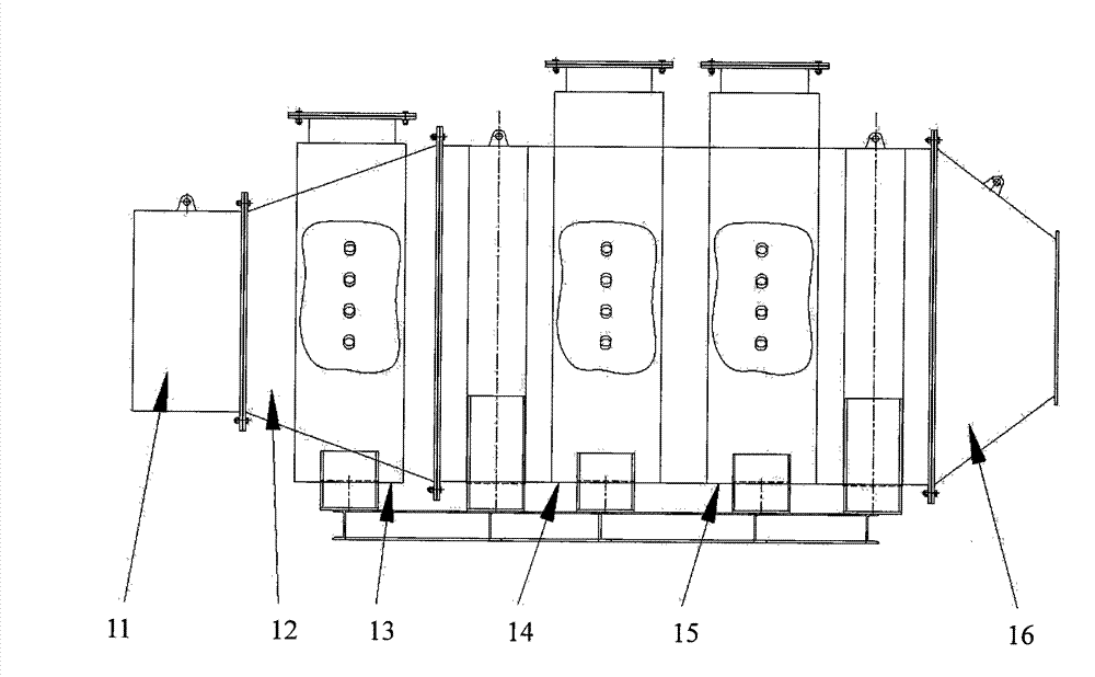
[0020] Step 2. Pass the above-mentioned ammonia solution or urea solution into the external ammonia temperature booster mixer 1, pass through the injection section 11, and enter the atomization section 12 for atomization.

[0021] Step 3. After the atomized ammonia solution or urea solution passes through the first heating section 13, the second heating section 14, and the third heating section 15 in sequence, it undergoes staged heating and gasification, and finally enters the diversion pressurization section 16, Ammonia gas with uniform temperature and pressure is formed. In each heating section, a heat exchanger is provided for heat exchange and temperature increase. In this embodiment, in order to protect the environment and save energy, the gasification heat source adopts the high-temperature flue gas and the medium-temperature...


PUM


Abstract

The invention discloses a high-efficiency ammonia-method denitration process and a high-efficiency ammonia-method denitration device. The process comprises the following steps of: first atomizing in advance the aqueous solution of ammonia or urea solution at the normal temperature, then performing high-temperature gasification and pressurization on the atomized aqueous solution of ammonia or urea solution, spraying the treated aqueous solution of ammonia or urea solution into a denitration reaction area of a smoke generation source, allowing the sprayed aqueous solution of ammonia or urea solution to be fully mixed, contact and react with smoke by using an ammonia temperature-increasing and pressurizing mixer. According to the invention, the atomization and gasification of the aqueous solution of ammonia or urea solution are performed in advance and high-temperature ammonia is introduced into the reaction area of the smoke generation source only after being fully and stably mixed, which improves the denitration effect by about 70 percent, maximally by 85 percent, and raises the effective reaction temperature of conventional selective non-catalytic reduction (SNCR) to 800 to 1,100 DEG C; therefore, the device can be called high-efficiency high-temperature ammonia-method denitration (HE-SNCR) system. Moreover, due to the adoption of ammonia-method selective non-catalytic reduction reaction, the process also can achieve the denitration effect under the condition of high dust thickness, and the denitration effect is better than that of selective catalytic reduction (SCR) or other post-treatment sections (low-dust thickness and low-water content).

Description

technical field [0001] The invention relates to the field of flue gas denitrification, in particular to a process and device for non-coal contact ammonia denitrification (SNCR). Background technique [0002] The effective denitrification temperature of the existing SNCR system is between 850-1050°C. The system adopts the non-coal contact ammonia method for denitrification. The ammonia liquid or urea solution with a water content of 80% is directly sprayed into the temperature reaction at room temperature through high-pressure steam or compressed air. The atomization in the area is in contact with the flue gas for denitrification. In this process, the atomized ammonia liquid or urea solution at room temperature directly exchanges heat with the high-temperature flue gas in the high-temperature reaction zone, which will cause sudden cooling in the high-temperature reaction zone, and the temperature of each area in the high-temperature reaction zone will be uneven, resulting in ...

Claims


Application Information

Patent Timeline
Patent Type & Authority Patents(China)
IPC IPC(8): B01D53/76B01D53/56
Inventor 张作保
Owner 东莞兆能环境科技有限公司
Learn More