Subsurface flow constructed wetland system of secondary effluent from sewage treatment plant and application thereof

A technology for a constructed wetland system and a sewage treatment plant, applied in the field of water treatment, can solve the problems of backward technology, expensive membrane modules, complicated operation management, etc. Effect

Inactive Publication Date: 2010-12-01
CHINA UNIV OF MINING & TECH (BEIJING)
View PDF4 Cites 26 Cited by
  • Summary
  • Abstract
  • Description
  • Claims
  • Application Information

AI Technical Summary

Problems solved by technology

[0002] Although the secondary treatment of urban sewage treatment plants has reduced various pollutants in the sewage to a large extent, the relative concentration of N, P and other pollutants in the effluent is still high, and the C/N is low
When these pollutants enter the receiving water body along with the effluent from the sewage plant, it is easy to cause eutrophication of the receiving water body
[0003] In the prior art, the advanced treatment processes of urban sewage treatment plants mainly include membrane bioreactor (MBR) process, biological aerated filter (BAF) process and CASS process, etc., which are backward in process, large in infrastructure investment, and difficult to operate. Disadvantages such

Method used


Image

  • Subsurface flow constructed wetland system of secondary effluent from sewage treatment plant and application thereof
  • Subsurface flow constructed wetland system of secondary effluent from sewage treatment plant and application thereof
  • Subsurface flow constructed wetland system of secondary effluent from sewage treatment plant and application thereof

Examples


specific Embodiment

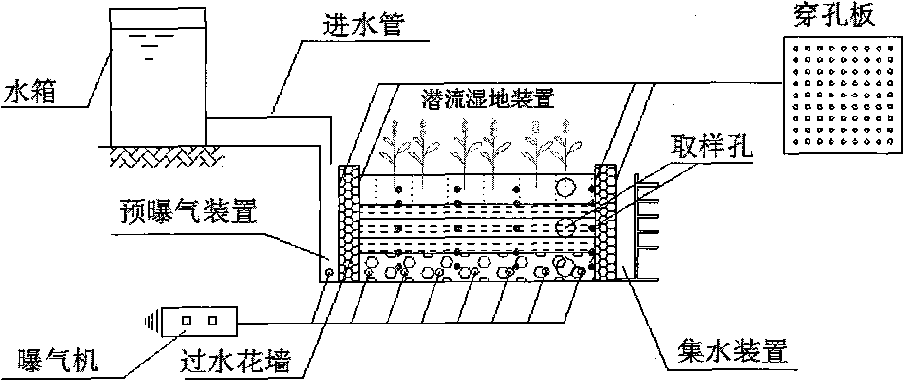
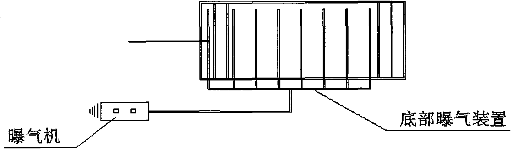
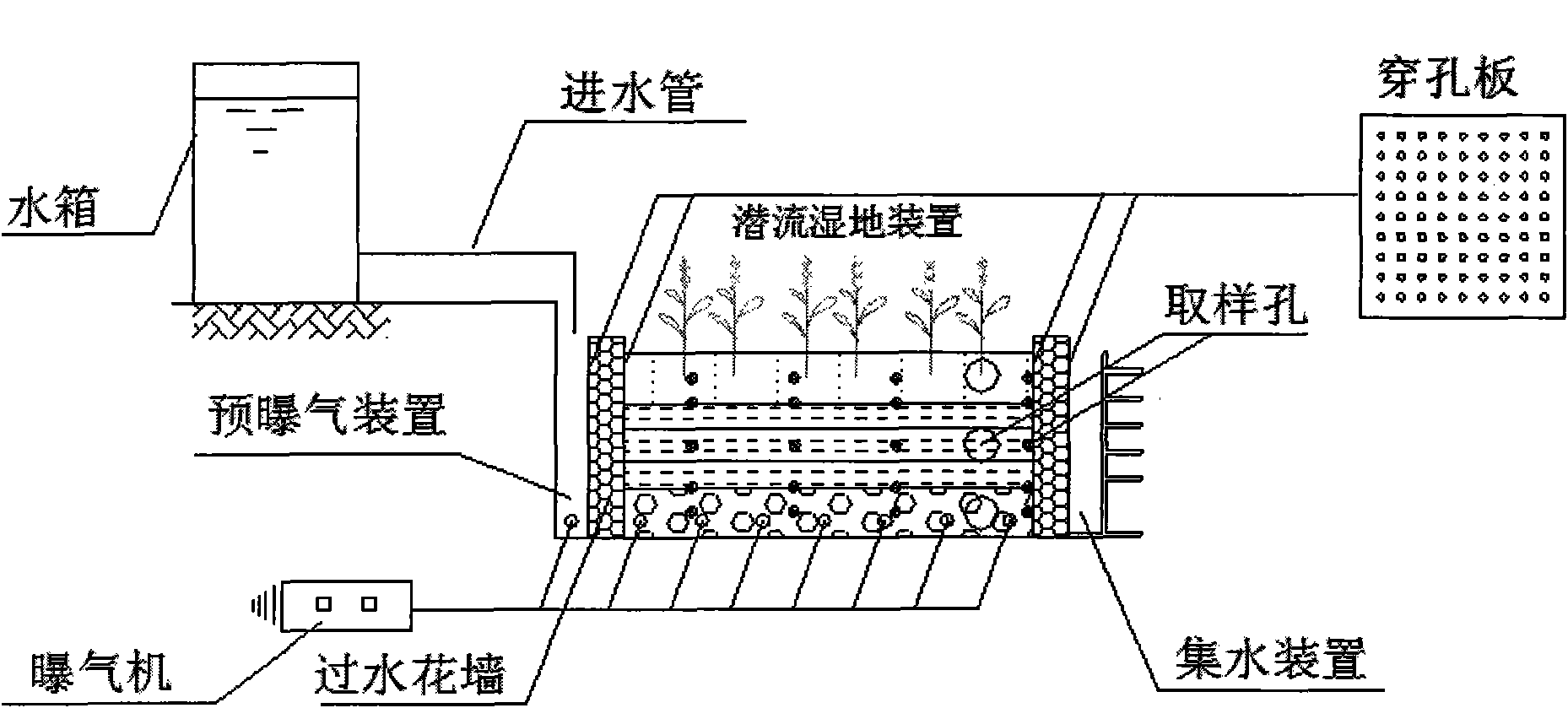
[0028] Such as figure 1 , figure 2 As shown, the subsurface flow constructed wetland system of the present invention is to allow the sewage to pass through the subsurface flow constructed wetland after pre-aeration, and the influent load is 0.6-1.2m 3 / (m 2 · Within the scope of d), obtain clear water that meets the Class III standard of "Surface Water Environmental Quality Standard (GB3838-2002)".

[0029] The pre-aeration device of the present invention is a box structure, an aeration pipe connected to an aerator is arranged at the bottom of the box, and small holes with the same diameter are evenly punched on the aeration pipe. The volume ratio of the pre-aeration device and the subsurface constructed wetland device is 1 / 12-1 / 8, the inner diameter of the circular tube is 8-12mm, and the diameter of the small holes on the circular tube is 2-4mm. According to the needs, the aerator can choose the appropriate model.

[0030] The subsurface flow wetland device and the pre-...


PUM


Abstract

The invention discloses a subsurface flow constructed wetland system of secondary effluent from a sewage treatment plant and an application thereof, and the subsurface flow constructed wetland system comprises a subsurface flow constructed wetland device, water passing tracery walls are respectively arranged on the water inlet side and the outer outlet side of the subsurface flow constructed wetland device, the water passing tracery walls are provided with water seepage holes, a wetland matrix and wetland plants are arranged between the water passing tracery walls on the two sides, and a bottom artificial aeration device is arranged at the bottom part of the subsurface flow constructed wetland device; a pre-aeration device is arranged outside the water passing tracery wall on the water inlet side, and a water collection device is arranged outside the water passing tracery wall on the water outlet side; and a high-level water tank is arranged on the water inlet side, the horizontal position of the high-level water tank is higher than the pre-aeration device and the subsurface flow constructed wetland device, and the high-level water tank is communicated with the pre-aeration device through a water inlet pipe. The subsurface flow constructed wetland system has the advantages of simple structure, low energy consumption, low cost, high nitrogen and phosphorus removal efficiency, small occupied area, convenient operation management, convenient sampling and the like. The subsurface flow constructed wetland system is particularly applicable to treatment of the secondary effluent of the urban sewage treatment plants and applicable to the treatment of other micro-polluted water.

Description

technical field [0001] The invention relates to a water treatment technology, in particular to an underflow artificial wetland system for secondary outlet water of a sewage treatment plant and its application. Background technique [0002] Although the secondary treatment of urban sewage treatment plants has reduced various pollutants in the sewage to a large extent, the relative concentration of N, P and other pollutants in the effluent is still high, and the C / N is low. When these pollutants enter the receiving water body along with the effluent from the sewage plant, it is easy to cause eutrophication of the receiving water body. [0003] In the prior art, the advanced treatment processes of urban sewage treatment plants mainly include membrane bioreactor (MBR) process, biological aerated filter (BAF) process and CASS process, etc., which are backward in process, large in infrastructure investment, and difficult to operate. High cost, unsatisfactory water quality after t...

Claims


Application Information

Patent Timeline
IPC IPC(8): C02F9/14C02F3/32C02F3/34
CPCY02W10/10
Inventor 何绪文张春晖王昊刘俐媛王建兵贾建丽
Owner CHINA UNIV OF MINING & TECH (BEIJING)
Why Eureka
Try Eureka