Method for removing shells from sea sand and a separation device using same

A separation device and shell technology, applied in wet separation, solid separation, chemical instruments and methods, etc., can solve the problems of high cost, reduction of concrete strength and durability, waste of resources, etc., and achieve good separation effect and long service life , the effect of low operating costs

Inactive Publication Date: 2010-12-15
陈惠玲 +2
View PDF5 Cites 6 Cited by
  • Summary
  • Abstract
  • Description
  • Claims
  • Application Information

AI Technical Summary

Problems solved by technology

In the practice of coastal sea sand treatment in my country, the screen is generally used to remove shells larger than a certain particle size. The defect of this method is that when the shells larger than the set particle size are screened out, the sea sand larger than the particle size will be screened at the same time. , and shells smaller than this particle size cannot be removed, so the treated sea sand also contains shells. If it is directly used in construction together with sea sand, it will reduce the strength and durability of concrete and form a potential safety hazard
[0004] Because the shells in sea sand are difficult to get rid of, it is difficult to use sea sand for high-grade concrete, and sea sand with shell content exceeding the specification requirements cannot be used as construction sand, resulting in a waste of resources
[0005] Sea sand desalination has been carried out in coastal areas of my country for many years. Many studies and attempts have been made on how to remove sea sand shells smaller than the aperture of the screen. Some people try to use a spiral classifier for processing, but the sea sand after treatment still contains a lot shells; there is also the use of chemical treatment, which not only costs a lot, but also causes environmental pollution. The treatment effect of various methods for removing shells in sea sand is not ideal, and no better treatment method has been found so far.

Method used


Image

  • Method for removing shells from sea sand and a separation device using same
  • Method for removing shells from sea sand and a separation device using same
  • Method for removing shells from sea sand and a separation device using same

Examples


Embodiment 1

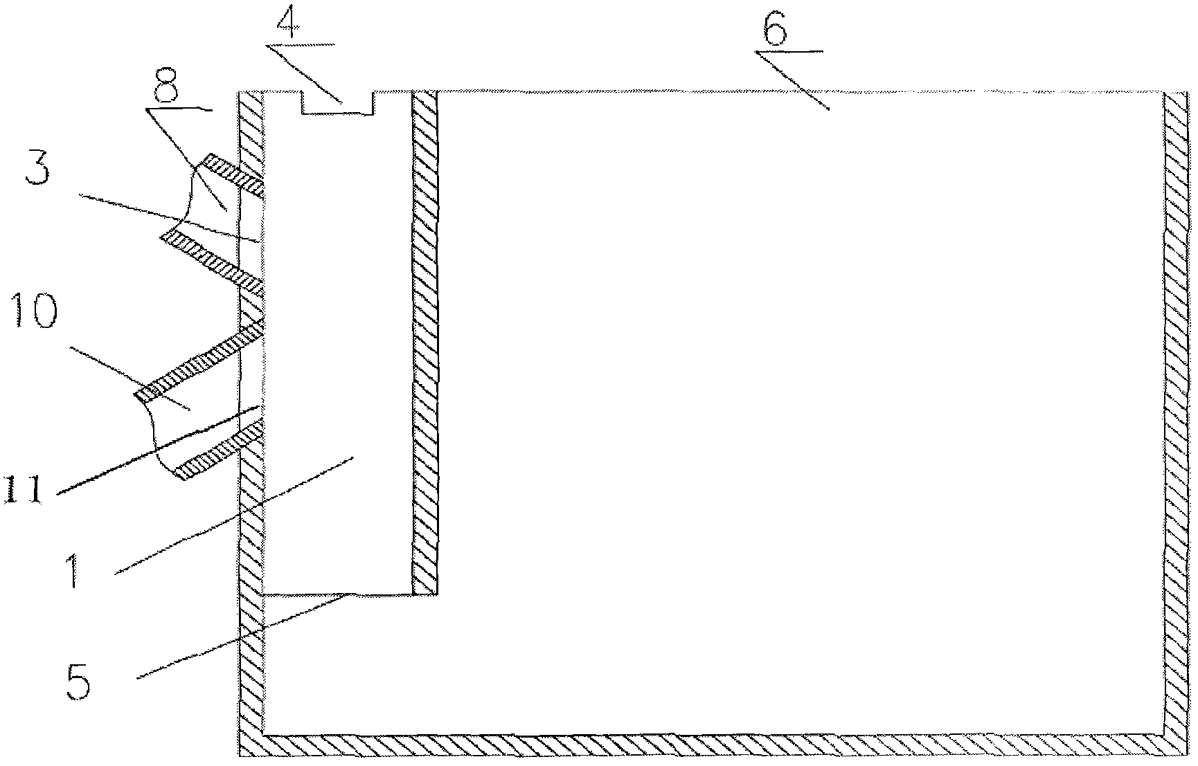
[0050] like figure 1 The separation device shown in this example includes a collection tank 6, a flow channel pipe 1 vertically arranged in the collection tank 6, and a tubular body 8 as a sand inlet channel. The water source pipe 10 extends through the wall of the flow pipe 1 obliquely upwards into the middle and lower part of the flow pipe 1, and forms a water inlet 11 on the flow pipe to provide upward water flow.

[0051] The tubular body 8 of the separation device of the present invention is located above the water source pipe 10, and the tubular body 8 passes through the wall of the flow pipe 1 obliquely downwards and extends into the middle and upper part of the flow pipe 1, forming an inlet on the flow pipe 1. The sand mouth 3, the sand inlet 3 is higher than the water inlet 11.

[0052] The bottom opening of the flow pipe 1 of the separation device of the present invention is used as the sand outlet 5 , and the flow pipe 1 communicates with the collection tank 6 thro...

Embodiment 2

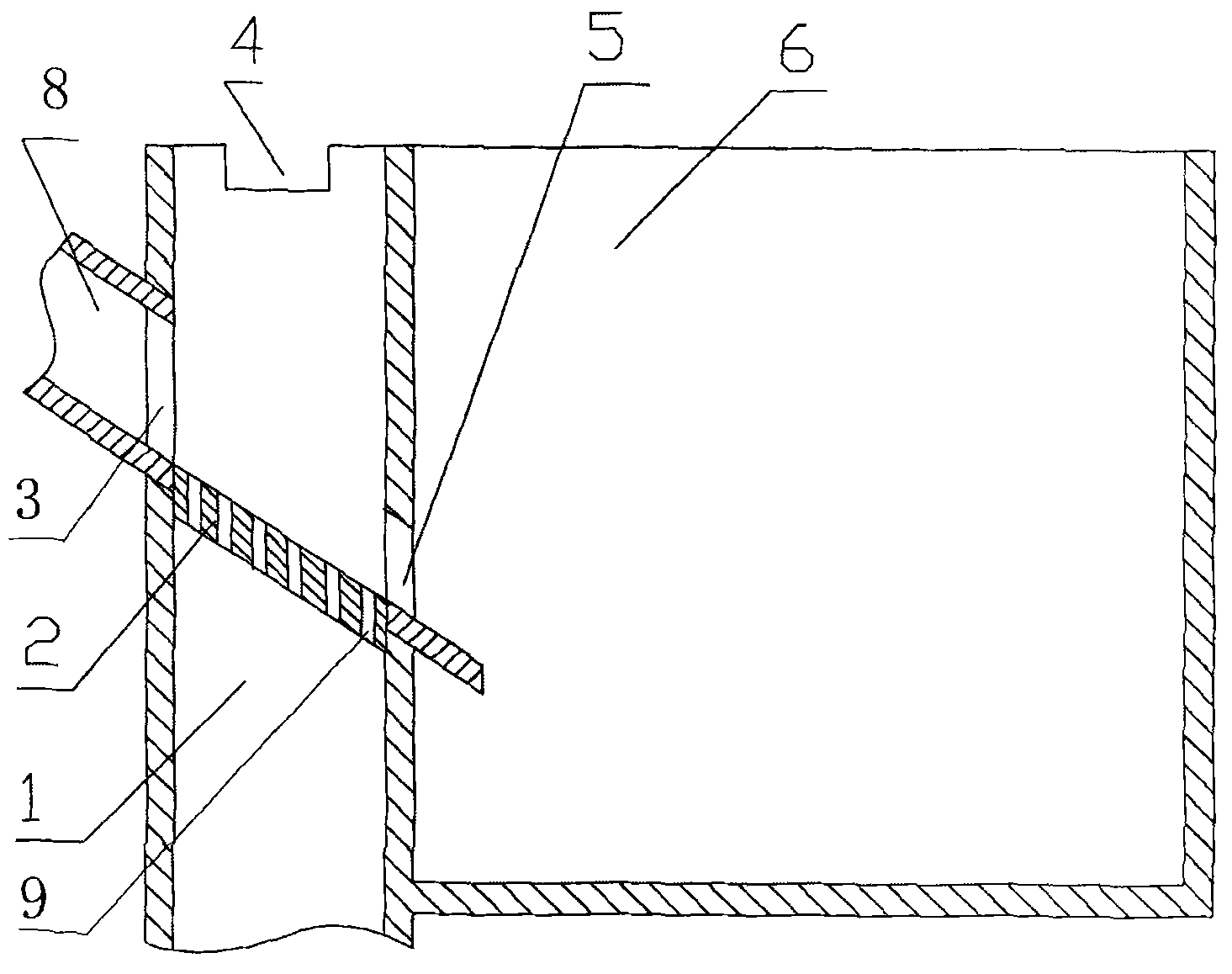
[0061] like figure 2 The separation device shown in this example includes a collection tank 6, a vertically arranged flow channel pipe 1 and a tubular body 8 as a sand inlet channel. The lower end of the flow channel pipe 1 communicates with the water source pipe (not shown in the figure), and the water source pipe is used to provide an upward water flow in the flow channel pipe; an inclined lining plate 2 is fixed around the inner wall of the middle part of the flow channel pipe 1, The vertical direction on the backing plate 2 is densely covered with through-holes 9 passing through from top to bottom.

[0062] The tubular body 8 passes through the wall of the flow channel pipe 1 in an oblique downward direction and extends into the middle and upper part of the flow channel pipe 1, forming a sand inlet 3 on the side wall of the flow channel pipe 1. The sand inlet 3 in this example is located at On the side wall of the flow channel pipe at the upper part of the high-end side ...

Embodiment 3

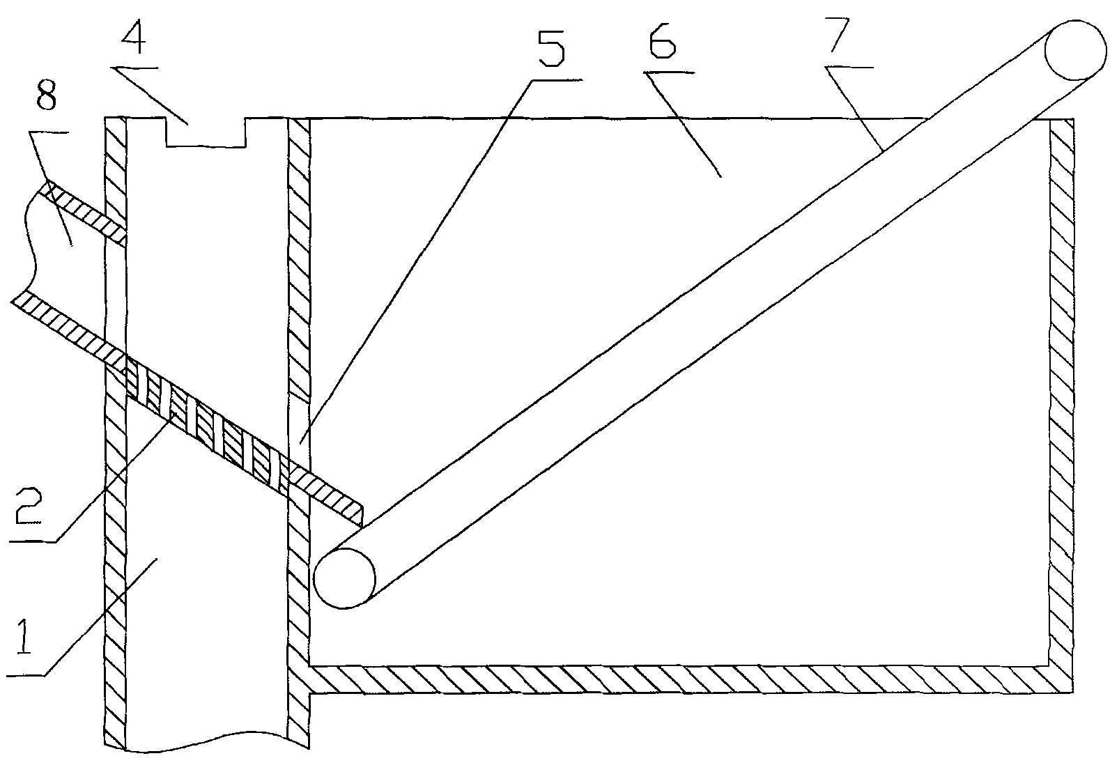
[0070] like image 3 The difference between the present example shown and Embodiment 2 is that the separation device also includes a belt conveyor (not shown in the figure), and the conveyor belt 7 of the belt conveyor is arranged in the collection tank obliquely upward, and the low end of the conveyor belt 7 is at the sand outlet 5 Below, the high end of the conveyor belt 7 stretches out of the pool mouth of the collection pool, and the belt conveyor will transmit the sea sand falling into the conveyor belt from the sand outlet to the outside of the collection pool in real time through the conveyor belt 7.


PUM


Abstract

The invention provides a method for removing shells from sea sand and a separation device using the same. The invention combines the screening method and the hydraulic classification method and artificially makes a Newtonian fluid field, so that a dispersed phase (shells) and a continuous phase (sea sand) make relative movement in an artificial fluid field, and the shells are enabled to float upwards, thereby separating the shells from the sea sand. The separation device of the invention has the advantages of simple structure, low investment, low operating cost, favorable separating effect and long service life. By combining machinery and hydraulic power, the method has the advantages of low cost, no environment pollution; and by combining hydraulic classification and screening, the method can separate the shells from the sea sand, and has the advantages of low operating cost and favorable separating effect.

Description

technical field [0001] The invention relates to the field of sea sand treatment, in particular to a method for removing shells in sea sand and a separation device for removing shells in sea sand by using the method. Background technique [0002] With the rapid development of my country's economy and the increasing scale of construction, especially the rapid advancement of the urban process in the southeast coastal areas, many coastal cities are facing the plight of exhaustion of river sand resources. With the dwindling of river sand resources and the enhancement of people's understanding of the river bed and ecological damage caused by river sand mining, it will become an inevitable trend for future construction sand to use desalinated sea sand for urban construction. [0003] Sea sand has been used in construction for a long time at home and abroad. At present, more than 90% of the sand used in construction in Japan is treated sea sand. Most of the shells contained in sea ...

Claims


Application Information

Patent Timeline
Patent Type & Authority Applications(China)
IPC IPC(8): B03B7/00B03B5/64
Inventor 刘辉文
Owner 陈惠玲
Why Eureka
Try Eureka