Solar warming, water-heating, refrigeration and illumination device

A lighting device, solar energy technology, applied in the field of solar energy technology, can solve problems such as normal heating

Inactive Publication Date: 2010-12-15
陈仁春
View PDF0 Cites 3 Cited by
  • Summary
  • Abstract
  • Description
  • Claims
  • Application Information

AI Technical Summary

Problems solved by technology

[0003] In order to overcome the problem that in the process of solar heating, electricity cannot be used for normal heating, hot water, heating, and cooling due to freezing, and electricity is used for driving power consumption during normal work, the invention provides a solar heating, hot water, cooling, The lighting integrated device improves the above deficiencies and increases the functions

Method used


Image

  • Solar warming, water-heating, refrigeration and illumination device
  • Solar warming, water-heating, refrigeration and illumination device
  • Solar warming, water-heating, refrigeration and illumination device

Examples


Embodiment 1

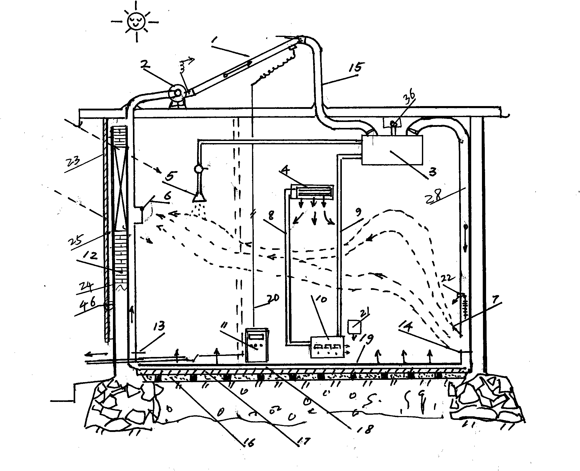
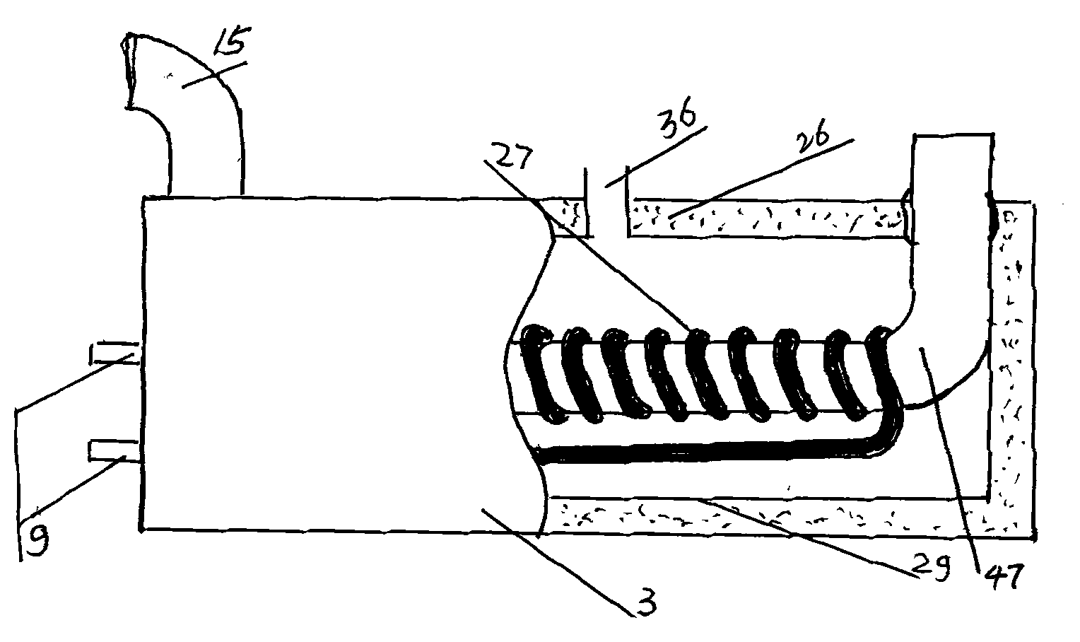
[0021] figure 1 The air preheater 46 composed of the sun panel 23, light-absorbing layer 24, and air chamber 25 is installed on the south side of the house and is mainly used to match the solar elevation angle in winter to improve the photothermal effect, and at the same time, it can inhale fresh air, which is inhaled by the DC electric fan 2 Photovoltaic heat collector 1. Due to the light and heat of sunlight and the photoelectric conversion effect of photovoltaic electricity, current is supplied to the DC electric fan to run, and the air heated twice enters the thermal insulation heat exchanger 3 through the hot air pipe 15 and passes through the heat exchanger. The pipe 47 releases heat to the water in the thermal insulation heat exchanger 3, so that the water increases the waste heat and releases the hot air to the room through the hot air outlet 7 of the hot air output pipe 28. Then enter the photovoltaic photothermal heat collector 1 and then warm through the hot air pip...

Embodiment 2

[0027] Figure 8 It is a system diagram of heat-air conduction heating, medium conduction refrigeration, and photovoltaic circuit of the device of the present invention. Figure 8 The medium photovoltaic thermal collector 1 generates electricity under sunlight F, the current passes through the ammeter A to charge the battery pack XD through the switch K2, and the current returns to the negative terminal of the photovoltaic thermal collector 1 to complete the charging work. The electric energy is stored in the battery pack XD, and the stored electric energy is turned on by the switch K3 at night to make the lighting LED illuminate. During the day, the switches K1 and K2 are turned on, and the electric energy generated by the photovoltaic photothermal collector is applied synchronously with the electric energy of the battery XD, and the switch is turned on At K4, the DC fan works for heating, when the switch K1 is turned on, the DC compressor unit D starts, and the refrigeration...

Embodiment 3

[0029] Figure 8 Among them, the refrigerant medium circuit is different from the conventional refrigeration and air-conditioning system in that the compressor is completed by direct current to reduce the function and cost of the inverter. In its working scheme, the switch K1 is turned on, the DC motor D rotates, and the rotating medium of the compressor Y is compressed Compressed by the condenser 21 to release heat into the heat preservation heat exchanger 3 to generate hot water, and then release cold air to the air conditioner evaporator 4 through the medium liquid receiver 40, filter 41, manual valve 42, and expansion valve 43 for refrigeration . The refrigerated medium returns to the compressor Y through the gas-liquid separator 44 to complete the cycle, that is, compressor Y→condenser 27→liquid receiver 40→filter 41→manual valve 42→expansion valve 43→evaporator for air conditioner 4→gas-liquid separator 44→compressor Y.

[0030] When lighting, you only need to turn on ...


PUM


Abstract

The invention discloses a solar warming, water-heating, refrigeration and illumination device. The device uses photovoltaic power generated by a solar photovoltaic-photothermal heat collector as drive energy, supplies afterheat generated by the heat collector to a room for warming in a hot air conduction way by a direct-current electric fan and generates hot water by a heat exchanger at the same time; when refrigeration is required, the electric power stored and being generated is used as motive power to start the operation of a refrigeration-heating system, and the generated cold or heat is released or stored; and when illumination is required, a power source stored in a battery can be supplied to a light-emitting diode (LED) which emits light, so that the aim of illumination is fulfilled. The device solves the energy source problem of areas without electric power or sites which have the electric power but needs energy conservation. Areas with plenty sunlight are ideal markets of the device.

Description

Technical field [0001] The invention relates to the application field of solar energy technology, that is, solar light heat and photoelectricity are applied to the solar energy technology integrating heating, cooling, hot water and lighting. Background technique [0002] At present, solar heating, cooling, hot water, and lighting technologies begin to go to the market, but they have many disadvantages in use. The above solar energy technologies have few basic functions, and must have external energy when doing work externally. For example, they need to cooperate with external energy such as electric energy and gas; and in work, they need antifreeze measures; they cannot make full use of solar energy, etc. Contents of the invention [0003] In order to overcome the problem that in the process of solar heating, electricity cannot be used for normal heating, hot water, heating, and cooling due to freezing, and electricity is used for driving power consumption during normal w...

Claims


Application Information

Patent Timeline
IPC IPC(8): F24J2/20F24D3/00F24F5/00H02N6/00F24S10/50H02S40/44
CPCY02E10/44Y02E10/50Y02E10/60
Inventor 陈仁春
Owner 陈仁春
Why Eureka
Try Eureka