Gas metering monitoring device and monitoring method
A gas measurement and monitoring device technology, applied in the direction of color/spectral characteristic measurement, etc., can solve the problems of low measurement and monitoring accuracy, and achieve the effects of high stability, high reliability and improved accuracy
- Summary
- Abstract
- Description
- Claims
- Application Information
AI Technical Summary
Problems solved by technology
Method used
Image
Examples
Embodiment 1
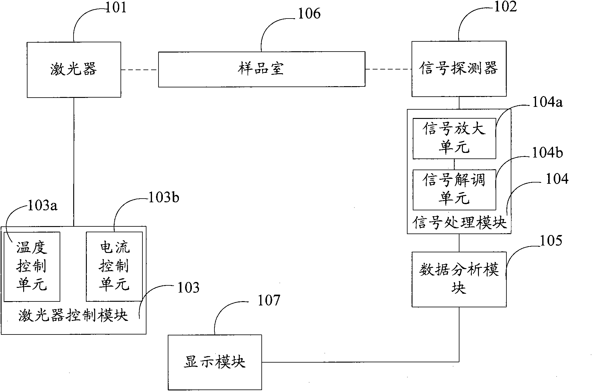
[0059] figure 1 A schematic structural diagram of a gas detection device provided in Embodiment 1 of the present invention, the device includes:
[0060] Laser 101 , signal detector 102 , laser control module 103 , signal processing module 104 , data analysis module 105 and sample chamber 106 .
[0061] The laser control module 103 is connected to the laser 101 and is used to drive the laser 101 to emit a laser with a specific wavelength to the sample gas in the sample chamber 106 .
[0062] The laser 101 may be a tunable diode laser, specifically: a semiconductor distributed feedback laser or a semiconductor vertical cavity surface emitting laser.
[0063] A sample gas is passed into the sample chamber 106 . The sample chamber 106 can be a single sample chamber or a multiple reflection sample chamber, and the multiple reflection sample chamber can specifically be a double reflection sample chamber, a Herriott type or a White type multiple reflection sample chamber. The mul...
Embodiment 2
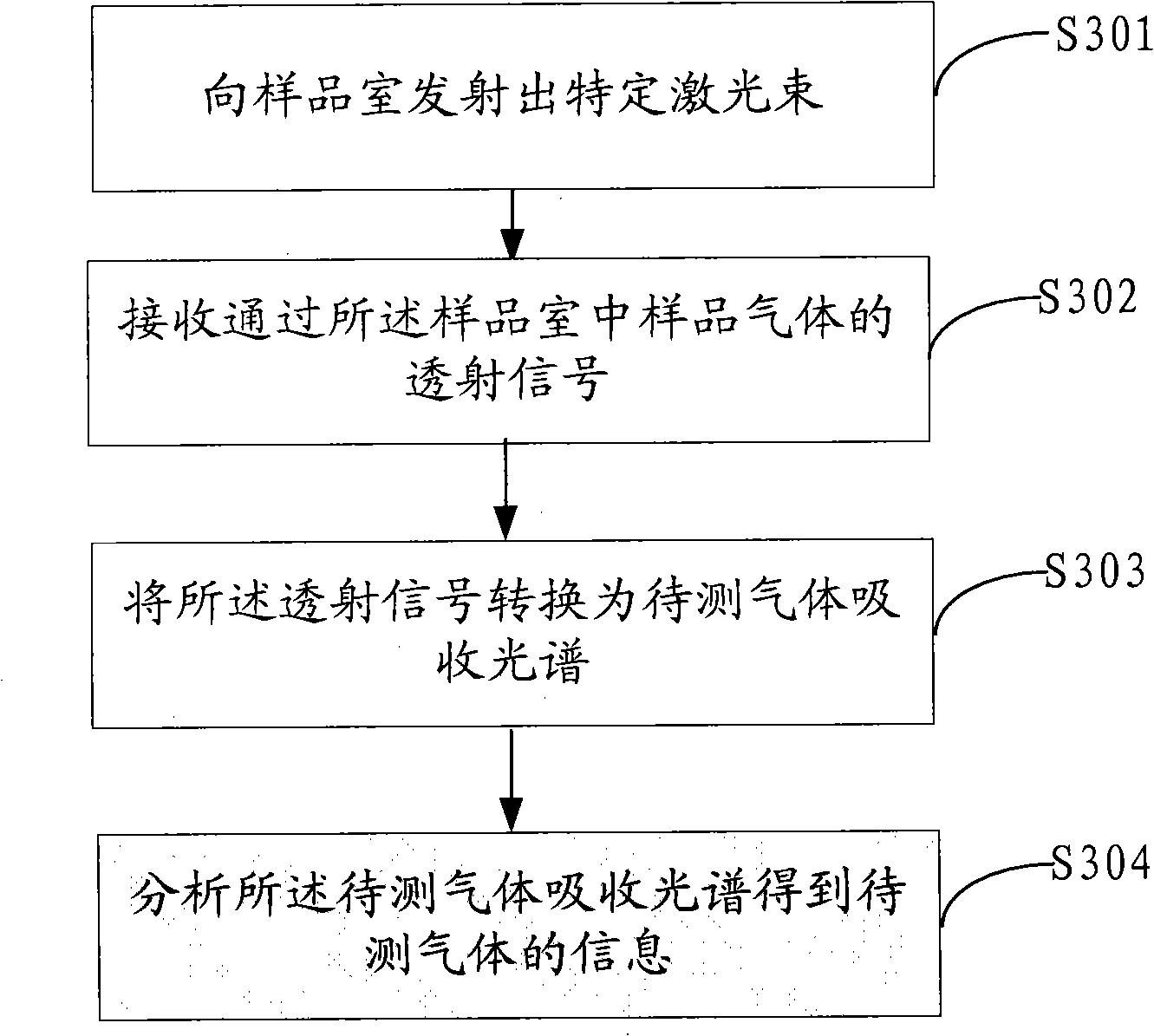
[0112] see image 3 As shown, it is a schematic flow chart of the gas metering monitoring method provided in this embodiment, and the method specifically includes the following steps:
[0113] S301, emitting a specific laser beam to the sample chamber;
[0114] S302, receiving a transmission signal through the sample gas in the sample chamber;
[0115] S303, converting the transmission signal into an absorption spectrum of the gas to be measured;
[0116] S304, analyzing the absorption spectrum of the gas to be measured to obtain information about the gas to be measured.
[0117] Wherein, the conversion of the transmission signal into the absorption spectrum of the gas to be measured may specifically include:
[0118] converting the transmitted signal from an optical signal to an electrical signal;
[0119] The transmission signal is amplified, and the amplified transmission signal is demodulated to obtain the absorption spectrum of the gas to be measured.
[0120] As for...
Embodiment 3
[0123] Referring to the figure, it is a schematic flow chart of the gas metering and monitoring method provided in this embodiment. The method specifically includes the following steps:
[0124] S401, superimposing the low-frequency sawtooth wave and high-frequency sine wave to drive the laser to emit a specific laser beam to the sample chamber;
[0125] S402. Obtain a transmission signal containing high-frequency information passing through the gas to be measured in the sample chamber;
[0126] S403, converting the transmission signal into an absorption spectrum of the gas to be measured;
[0127] S404, acquiring the double frequency signal curve in the absorption spectrum line;
[0128] S405, analyzing the peak value of the double frequency signal to obtain the information of the gas to be measured.
[0129] Wherein, in order to make the obtained gas information to be measured more accurate, before analyzing the peak value of the frequency-doubling signal to obtain the inf...
PUM
 Abstract
Description
Claims
Application Information
 - R&D
- Intellectual Property
- Life Sciences
- Materials
- Tech Scout
- Unparalleled Data Quality
- Higher Quality Content
- 60% Fewer Hallucinations
Browse by: Latest US Patents, China's latest patents, Technical Efficacy Thesaurus, Application Domain, Technology Topic, Popular Technical Reports.
© 2025 PatSnap. All rights reserved.Legal|Privacy policy|Modern Slavery Act Transparency Statement|Sitemap|About US| Contact US: help@patsnap.com


