
Double-frequency microstrip antenna

A microstrip antenna and microstrip technology, applied in the direction of antennas, electrical short antennas, antenna components, etc., can solve the problems of unstable phase center of received signals, misalignment of phase centers, and influence on antenna receiving accuracy, so as to improve accuracy, The effect of reducing signal error and simple structure

Active Publication Date: 2010-12-15
GUANGZHOU HI TARGET SURVEYING INSTRUMENT CO LTD
View PDF3 Cites 20 Cited by
  • Summary
  • Abstract
  • Description
  • Claims
  • Application Information

AI Technical Summary

Problems solved by technology

Since the antenna adopts offset feed or side feed, it is easy to make the electrical phase center of the antenna not coincide with the geometric center when receiving signals. When the satellite moves or the dual-frequency microstrip antenna moves, the phase center of the received signal is unstable, making the The received signal has an error, which affects the receiving accuracy of the antenna
For the dual-band two-layer patch, not only is it easy to make the phase center of a single frequency band unstable, but it is also easy to make the phase centers of different frequency bands misaligned, so the dual-band two-layer patch antenna receives more The error of the signal is greater, and the accuracy of signal acceptance is lower

Method used

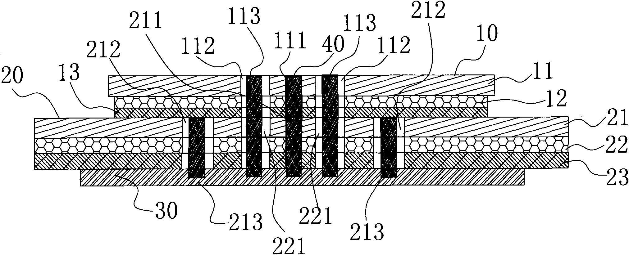

Image

  • Double-frequency microstrip antenna
  • Double-frequency microstrip antenna
  • Double-frequency microstrip antenna

Examples


Embodiment Construction

[0020] In order to make the present invention easier to understand, the present invention is further described below with reference to the accompanying drawings, but the embodiments in the accompanying drawings do not constitute any limitation to the present invention.

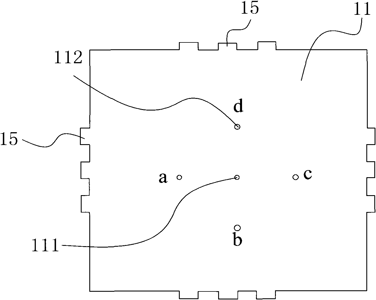
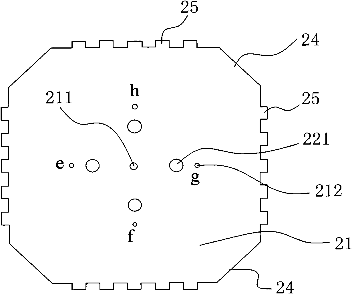
[0021] A dual-frequency microstrip antenna of the present invention, such as Figure 1 to Figure 3 As shown, it includes an upper-layer microstrip antenna 10 with an upper-layer patch 11, a lower-layer microstrip antenna 20 with a lower-layer patch 21, and a feed network 30 placed on the bottom layer, and an upper layer is provided at the geometric center of the upper-layer patch 11 The center hole 111, the lower layer center hole 211 is provided at the geometric center of the lower layer patch 21, and the dual-frequency microstrip antenna is also provided with a short-circuit pin 40, and the short-circuit pin 40 penetrates from the upper layer center hole 111 in sequence The upper-layer microstrip antenna 10 ...


PUM


Abstract

The invention discloses a double-frequency microstrip antenna, which comprises an upper-layer microstrip antenna with an upper-layer paster, a lower- layer of microstrip antenna with a lower-layer paster and a feed network located at the bottom layer. The geometric center of the upper-layer paster is provided with an upper-layer central hole, the geometric center of the lower-layer paster is provided with a lower-layer central hole, the double-frequency microstrip antenna is also provided with a short circuit pin which is connected with an earth wire of the feed network after sequentially penetrating into the upper-layer microstrip antenna from the upper-layer central hole and penetrating into the lower-layer microstrip antenna from the lower-layer central hole, and the short circuit pin is respectively electrically connected with the upper-layer paster and the lower-layer paster. In the invention, through fixing the geometric center of the upper-layer paster and the geometric center of the lower-layer paster together and connecting the upper-layer paster and the lower-layer paster with the earth wire of the feed network by the short circuit pin, the invention can stabilize the phase centers of the two frequency-band signals received by the double-frequency microstrip antenna, thereby reducing signal error of the double-frequency microstrip antenna and improving the signal receiving precision of the double-frequency microstrip antenna.

Description

technical field [0001] The present invention relates to an antenna, in particular to a dual-frequency microstrip antenna. Background technique [0002] The dual-band microstrip antenna can be used as a measurement antenna to simultaneously receive signals from the L1 frequency band of GPS (Global Positioning System) and signals from the L2 frequency band of GLONASS (Global Navigation Satellite System). The system receiver can be used in geodetic surveying, control surveying, real-time dynamic positioning, oceanographic surveying, channel surveying, dredging surveying, aviation flight positioning, remote sensing applications, offshore drilling positioning and other measurement systems. [0003] The existing dual-frequency microstrip antenna usually adopts a two-layer patch structure, and realizes circular polarization through offset feed or side feed. Since the antenna adopts bias feed or side feed, it is easy to make the electrical phase center of the antenna and the geomet...

Claims


Application Information

Patent Timeline
Patent Type & Authority Applications(China)
IPC IPC(8): H01Q1/00H01Q1/36H01Q13/08H01Q21/30
CPCH01Q9/0414
Inventor 廖定海鲍志雄吴多龙李庚禄李瑞
Owner GUANGZHOU HI TARGET SURVEYING INSTRUMENT CO LTD
Learn More