Driving system for light-emitting diode

A technology for light-emitting diodes and driving systems, applied in the field of light-emitting diode driving systems, can solve problems such as reducing system design flexibility and increasing system costs, and achieves the effects of saving external components, improving efficiency, and improving reliability

Active Publication Date: 2010-12-15
GIANTEC SEMICON LTD
View PDF2 Cites 12 Cited by
  • Summary
  • Abstract
  • Description
  • Claims
  • Application Information

AI Technical Summary

Problems solved by technology

[0008] However, the traditional current mode control LED drive system uses external compensation to ensure the

Method used


Image

  • Driving system for light-emitting diode
  • Driving system for light-emitting diode
  • Driving system for light-emitting diode

Examples


Embodiment approach

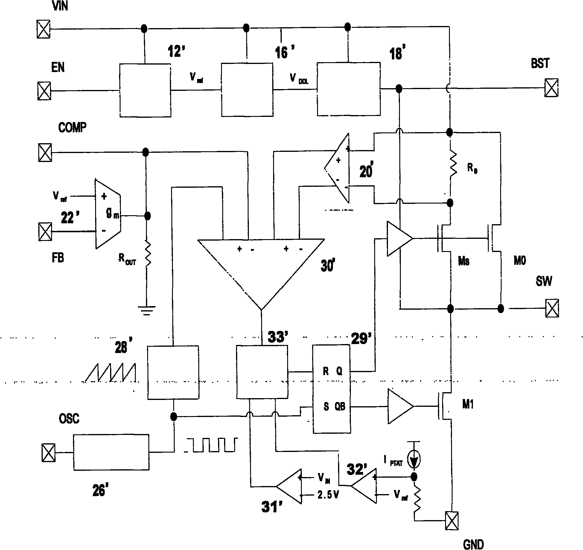
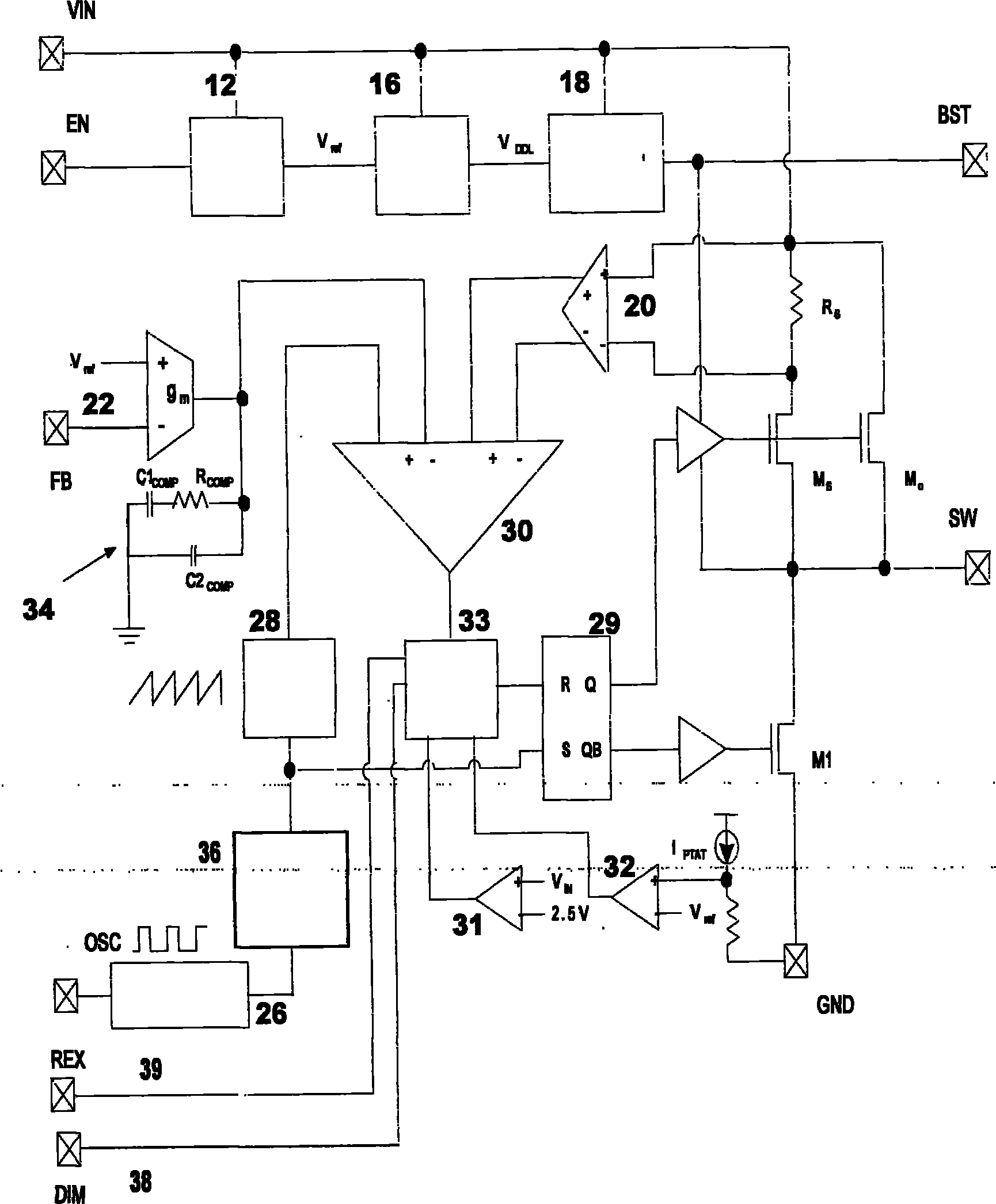
[0052] Such as figure 2 As shown, it is a circuit diagram of a light-emitting diode driving system, and the light-emitting diode driving system includes a circuit-connected reference bias module 12, a low-dropout voltage regulator 16, a bootstrap circuit 18, and a power switch tube M 0 and M S , inductor Rs, Schottky diode D1, current sense amplifier 20, PWM comparator 30, error amplifier 22, slope compensation circuit 28, logic circuit 33, RS latch 29, system oscillator 26, undervoltage lockout module 31 , and, thermal shutdown module 32;

[0053] The LED drive system sets the following pins: input voltage pin VIN, ground pin GND, feedback pin FB, pin SW connected to an external inductor, pin COMP connected to an external compensation circuit, and when grounded, the driver can be in The pin EN in the shutdown state and the bootstrap circuit pin BST;

[0054] The LED driver system also includes:

[0055] 1. An internal compensation module 34, the circuit of which is conne...


PUM


Abstract

The invention relates to a driving system for a light-emitting diode. The driving system is provided with an internal compensation module, a spread spectrum modulation module, a differential interference microscopy (DIM) pin and a frequency real-time executive (REX) pin, wherein the DIM pin is driven by an external logic pulse-modulated signal; and the frequency REX pin changes an internal clock of the light-emitting diode through an external resistor. The system has the advantages of realizing system stability by an internal compensation method, saving external components, effectively reducing electromagnetic noise by spread spectrum modulation, improving the efficiency of the driving system for the light-emitting diode by adopting a dimming function, achieving a heat compensation function, enhancing the reliability of the driving system for the light-emitting diode and changing the internal oscillation efficiency of the driving system for the light-emitting diode from outside by external frequency modulation.

Description

technical field [0001] The invention relates to a light-emitting diode drive system, in particular to a light-emitting diode drive system with functions of internal compensation, spread spectrum modulation, external frequency modulation and light adjustment. Background technique [0002] With the rapid development of optoelectronic technology and semiconductor technology, light-emitting diodes (LEDs) have gained more and more attention in many fields due to their long service life, high efficiency, and small size. [0003] Due to differences in the production process, the electrical characteristics of LEDs produced by different manufacturers can vary considerably. The voltage versus current characteristic curve of a light-emitting diode will affect the brightness and service life of the LED. So the design of the LED drive circuit is very important. [0004] Currently, the main LED driving system is implemented using pulse modulation (PWM) control. Buck type, pulse modulat...

Claims


Application Information

Patent Timeline
IPC IPC(8): H05B37/02
CPCY02B20/42Y02B20/40
Inventor 杨清张洪范仁永
Owner GIANTEC SEMICON LTD
Why Eureka
Try Eureka