Gas breaking and gas stripping linked double-phase vacuum underground water pumping in-situ repair method

A technology of vacuum suction and in-situ repair, which is applied in separation methods, chemical instruments and methods, and restoration of polluted soil, etc. Obvious and other problems, to achieve the effect of high processing efficiency

Active Publication Date: 2010-12-22
BC P INC CHINA NAT PETROLEUM CORP +2
View PDF1 Cites 22 Cited by
  • Summary
  • Abstract
  • Description
  • Claims
  • Application Information

AI Technical Summary

Problems solved by technology

[0005] The existing groundwater pollution remediation technology mainly has two disadvantages: (1) The existing technology is often only aimed at a single type of pollution, and cannot simultaneously treat pollutants that exist in various forms
For example, soil gas phase extraction can only deal with gas phase pollution, and other technologies can only be used for dissolved phase, residual phase and free phase pollutants, resulting in high treatment costs, complicated system configuration, and difficult operation and maintenance.
(2) The universality of the existing technology is not strong
However, this method is not perfect. The position of the air jet outlet of the pneumatic rupture tube is fixed, so the soil near the outlet position can only be repeatedly shattered, and the effect of promoting the movement of pollutants at various depths underground is not obvious, and the energy consumes a lot
In fact, this method also fails to provide a linkage operation scheme between pneumatic rupture and suction
Similarly, if the groundwater level is low and the free distance from the ground is relatively deep, the two-phase vacuum suction well will still fail to pump out pollutants.

Method used


Image

  • Gas breaking and gas stripping linked double-phase vacuum underground water pumping in-situ repair method
  • Gas breaking and gas stripping linked double-phase vacuum underground water pumping in-situ repair method
  • Gas breaking and gas stripping linked double-phase vacuum underground water pumping in-situ repair method

Examples


Embodiment Construction

[0043] The present invention will be described in detail below in conjunction with accompanying drawings and examples.

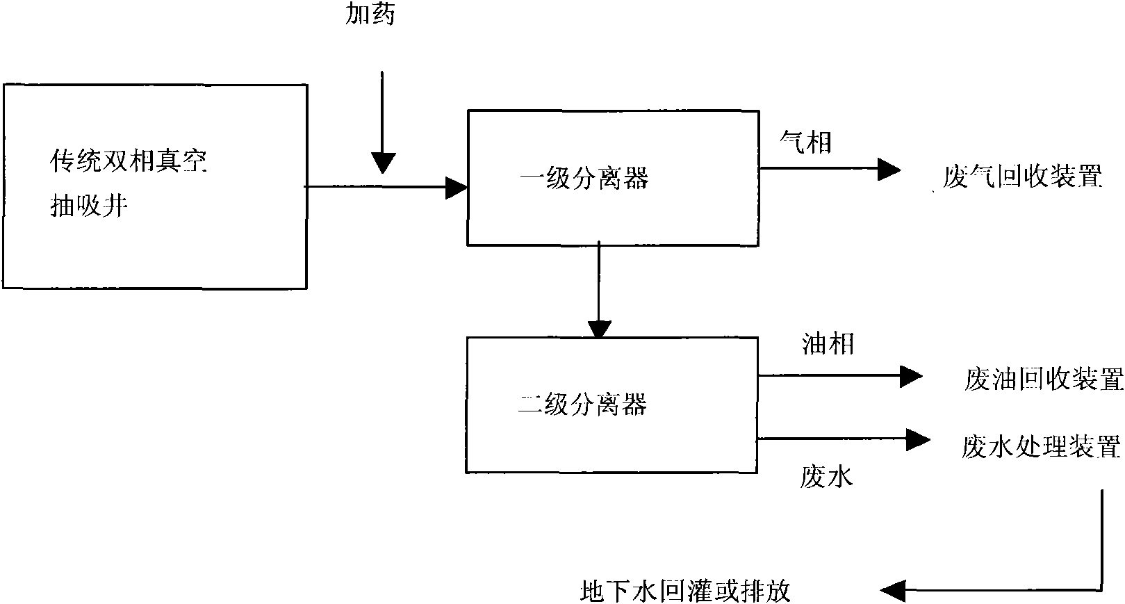
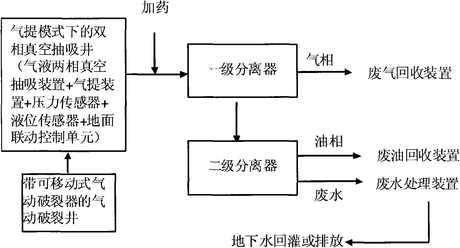
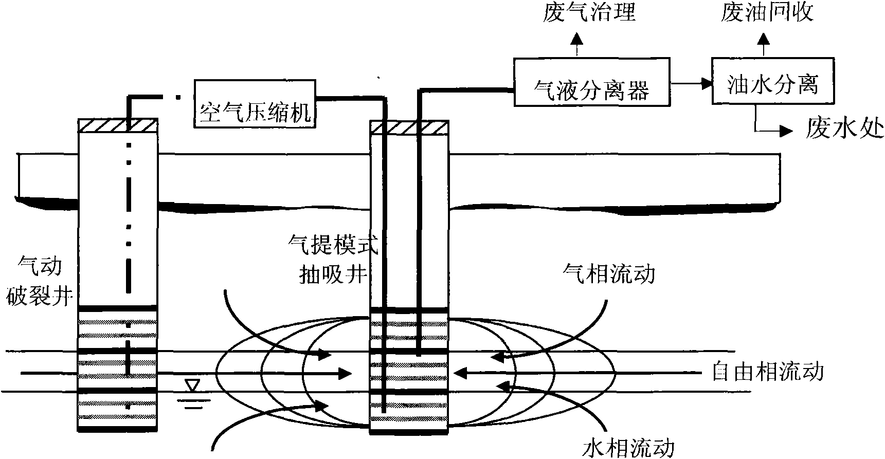
[0044] The present invention promotes the above-mentioned process and improves the extraction efficiency by respectively installing an air lift device in a two-phase vacuum suction well and setting a pneumatic fracturing well near the well. At the same time, the present invention provides a linkage scheme with air lift, vacuum suction and pneumatic fracturing, which can be automatically adjusted according to the changes in operating parameters in the wells equipped with suction and pneumatic fracturing to achieve an optimal combination of efficiency and cost . The monitoring and control of operating parameters are mainly realized by installing vacuum sensors, liquid level sensors and programming automatic control. The invented air breaking and air lifting coordinated two-phase vacuum suction method involves two-phase vacuum suction wells, pneumatic fracturi...


PUM


Abstract

The invention relates to oil and gas field ground engineering and environmental protection technology, and discloses a gas breaking and gas stripping linked double-phase vacuum underground water pumping in-situ repair method for repairing soil and underground water petroleum pollution. The method comprises the following steps of: immersing a gas stripping spray head below the underground water surface of a pumping well and in 0.1 to 0.2 meter far from the bottom of the well, placing a liquid level sensor below the well to sense the liquid level in the well, arranging a motor driven threaded shaft at the wellhead to repeatedly move a pneumatic breaker in the well up and down, and starting gas stripping when the liquid level is less than 10 meters; stopping pumping when the pressure is reduced to 0.02MPa, starting negative pressure pumping, raising the pressure of the pumping well to 0.085MPa, closing pneumatic breakage, and starting a pump of the pumping well. The method has high treatment efficiency, reaches 85 to 95 percent of treatment degree of a free phase of a petroleum pollutant, saves the investment by about 30 to 50 percent, saves the maintenance and management cost by 25 to 35 percent, and saves the running expense by 25 to 60 percent.

Description

technical field [0001] The invention relates to surface engineering technology and environmental protection technology of oil and gas fields, in particular to an in-situ repair method of ground water by gas breaking and gas lift linkage two-phase vacuum pumping for repairing oil pollution of soil and ground water. Background technique [0002] Environmental pollution and ecological damage caused by oil exploration, transportation, processing, sales and consumption are becoming more and more serious, which has attracted great attention from the industry and the whole society. Due to the many types of pollutants, the great harm, the high cost and long time of remediation, and the invisibility and complexity of the underground situation, the remediation and treatment of petroleum-based soil and groundwater pollution has become a worldwide problem. The development of efficient remediation technology for oil pollution in soil and groundwater has become one of the most important r...

Claims


Application Information

Patent Timeline
Patent Type & Authority Applications(China)
IPC IPC(8): C02F9/02C02F1/40B09C1/00
Inventor 谭倩黄国和王占生郭绍辉李恭臣秦肖生
Owner BC P INC CHINA NAT PETROLEUM CORP
Why Eureka
Try Eureka