RFID antenna with asymmetric structure and design method thereof

A technology of asymmetric structure and design method, applied in the field of radio frequency identification, can solve problems such as not having typical significance, and achieve the effect of improving antenna design efficiency, improving design efficiency, and avoiding blindness

Inactive Publication Date: 2010-12-22
AEROSPACE INFORMATION
View PDF4 Cites 10 Cited by
  • Summary
  • Abstract
  • Description
  • Claims
  • Application Information

AI Technical Summary

Problems solved by technology

Moreover, the 9554 antenna uses circular arcs and straight sides for asymmetry, which is not typical for RFID antennas.

Method used


Image

  • RFID antenna with asymmetric structure and design method thereof
  • RFID antenna with asymmetric structure and design method thereof
  • RFID antenna with asymmetric structure and design method thereof

Examples


Embodiment Construction

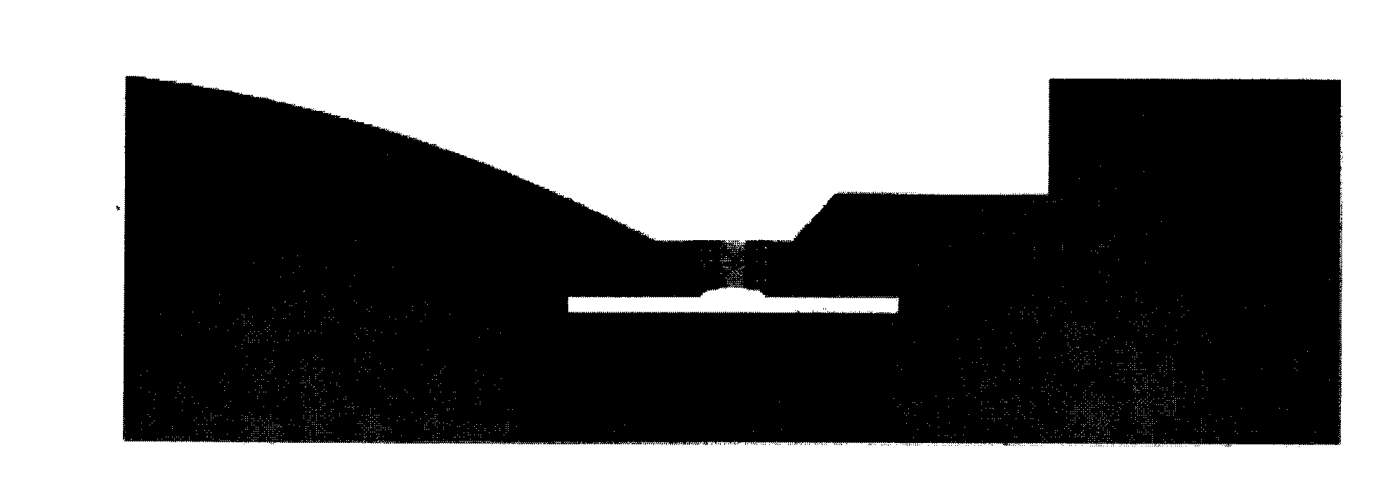
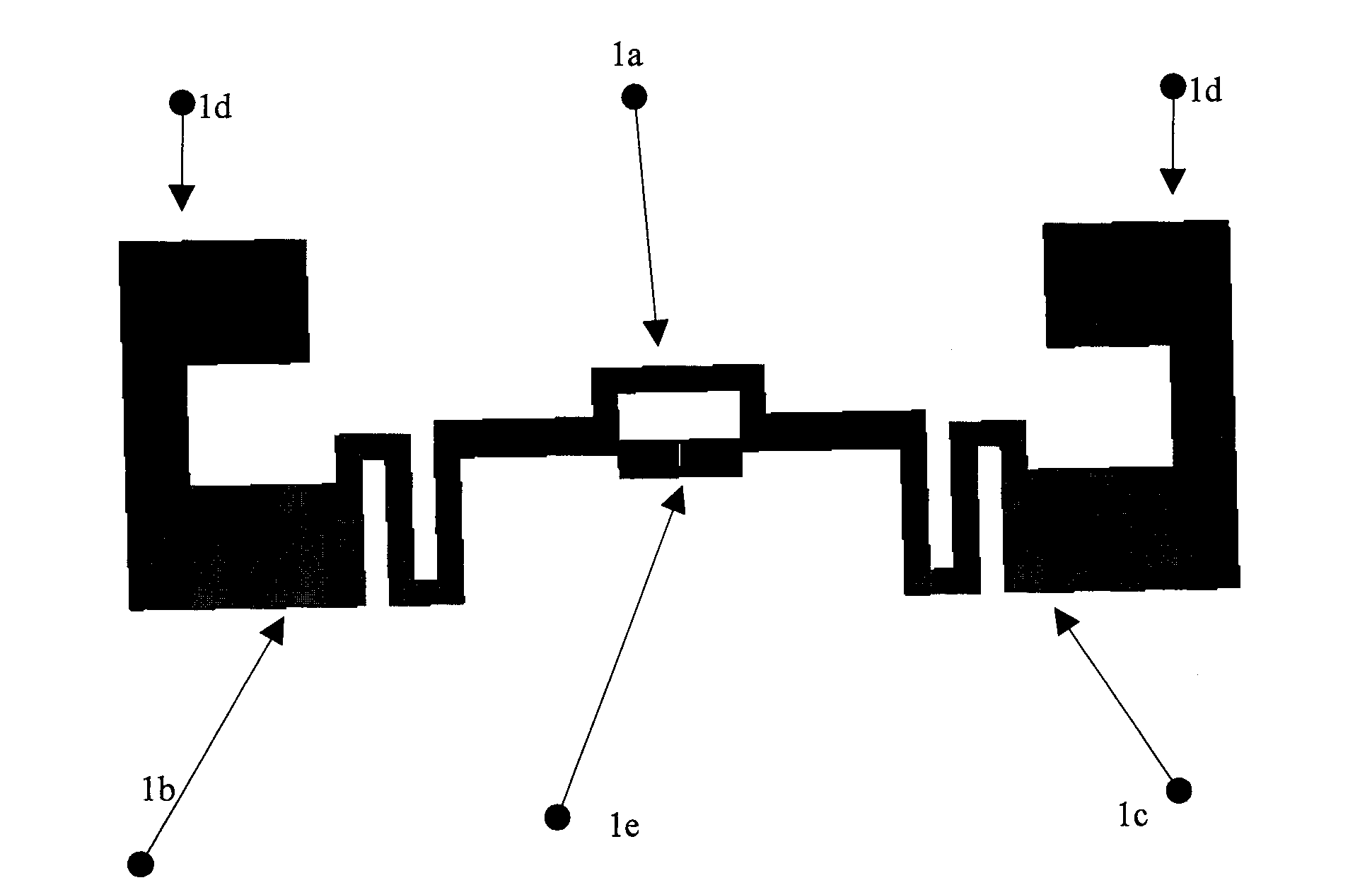
[0030] The structure of the RFID antenna of a kind of symmetrical structure that the present invention will use is as figure 2 As shown, it can be used for near-field and far-field antennas. The antenna can be divided into three parts, including: the ring structure in the center of the figure, the folded structure outside the block, and the outermost receiver of the figure. Among them, the ring structure in the center is used to receive near-field signals, prevent chip pin breakdown, and form inductive reactance; the folded structure is used for impedance matching; the outermost receiver mainly considers increasing the antenna gain, and generally has a large area. The shape and design method of this kind of antenna with a symmetrical structure have been discussed in the prior art, and the design method of the antenna with a symmetrical structure uses the existing technology in the present invention, so no further description is given. Any design method for symmetrically struc...


PUM


Abstract

The invention discloses a design method for an RFID antenna with an asymmetric structure. The method comprises the following steps of: determining target impedance of the antenna according to the use of the antenna and a chip; designing a first antenna with a symmetric structure, which meets the target impedance, namely designing an annular structure of the antenna, designing a folded structure with two symmetric folded patterns and designing a receiver on the outermost part; designing a second antenna with a symmetric structure, which meets the target impedance, by using the same mode, wherein the folded patterns of the second antenna are different from those of the first antenna and the annular structure and the receiver of the second antenna are the same as those of the first antenna; combining the designed symmetric antennas to form the antenna with the asymmetric structure in a mode that the two folded patterns in the folded structure of the antenna use the folded patterns of the first and second antennas respectively and the annular structure uses the common structure of the first and second antennas; and performing structural fine adjustment on the obtained antenna with the asymmetric structure. The method has good universality, and provides a guide for the design of the asymmetric structural antennas.

Description

technical field [0001] The present invention relates to radio frequency identification, in particular to RFID tag antenna and its design and manufacturing method. Background technique [0002] RFID radio frequency identification is a non-contact automatic identification technology. RFID technology can identify high-speed moving objects and can identify multiple tags at the same time, and the operation is fast and convenient. RFID is widely used in logistics, manufacturing, medical care, transportation, retail, defense and many more. UHF passive RFID tags have high operating frequency, long read-write distance, no external power supply, and low manufacturing cost. They have been widely used and may become mainstream products in the RFID field. At present, ultra-high frequency (UHF) passive tags have become one of the key research directions of RFID. [0003] However, the UHF antenna theory is still immature, and the antennas simulated by software based on radio frequency t...

Claims


Application Information

Patent Timeline
Patent Type & Authority Applications(China)
IPC IPC(8): H01Q1/24H01Q1/36H01Q7/02G06K19/07
Inventor 陈会军
Owner AEROSPACE INFORMATION
Why Eureka
Try Eureka