Brake pad polishing machine

A technology for brake pads and polishing machines, applied in the field of polishing technology, can solve the problems of accelerated wear of brake discs and brake pads, hidden dangers of normal use of braking systems, hidden dangers of motor vehicle safety, etc., so as to achieve less electricity bills and save equipment investment costs. , the effect of convenient operation

Inactive Publication Date: 2010-12-29
诸暨市瑞贝特机电科技有限公司
View PDF0 Cites 11 Cited by
  • Summary
  • Abstract
  • Description
  • Claims
  • Application Information

AI Technical Summary

Problems solved by technology

[0002] In the manufacturing process of automobile brake pads, since the friction base material of the brake pads is mainly glued together with the brake pads by mold casting, many uneven particles are easily left on the surface after the friction base material is formed, and even some Steel fibers emerge. If these irregular particles and steel fibers are not dealt with, when the brake pad is used, the braking force cannot be achieved due to the inability to achieve surface contact with the brake disc, resulting in uneven braking force. bring security risks
At the same time, due to the presence of irregular particles or even protruding steel fibers on the surface material, it will accelerate the abnormal wear of the brake disc, resulting in a vicious cycle of mutual accelerated wear of the brake disc and brake pads, which will bring hidden dangers to the normal use of the brake system.

Method used


Image

  • Brake pad polishing machine
  • Brake pad polishing machine
  • Brake pad polishing machine

Examples


Embodiment Construction

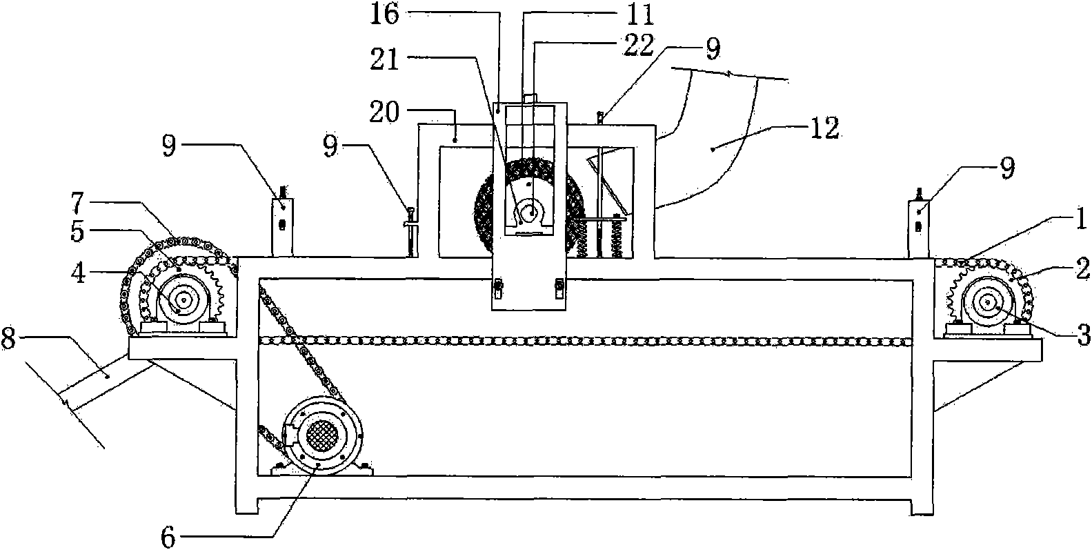
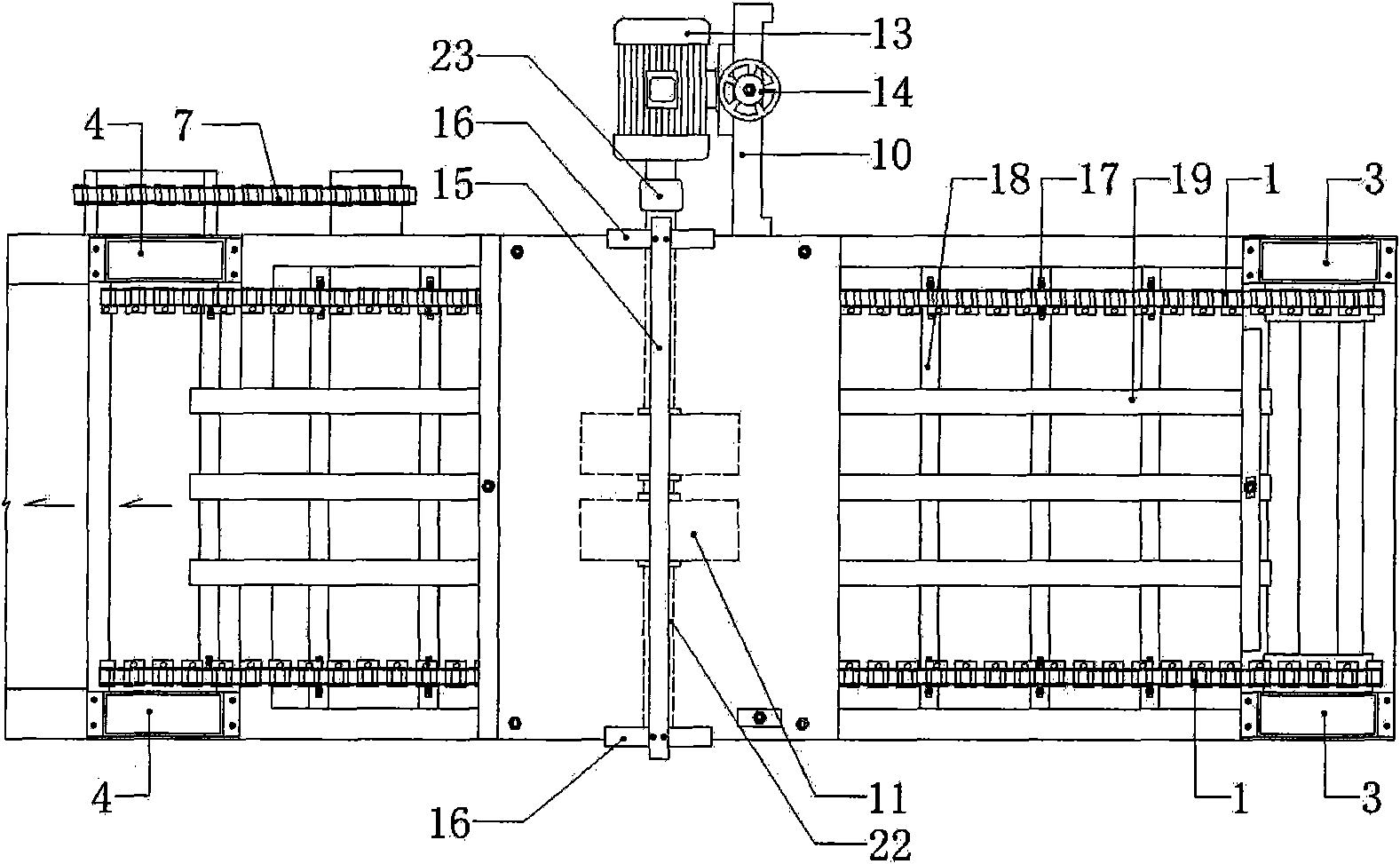
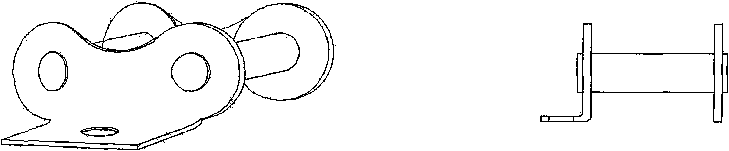
[0013] The brake pad polishing machine provided by the present invention mainly uses two transmission chains 1 on both sides of the polishing machine as a conveying device, and the transmission chains 1 on both sides are driven by the driving sprocket 5 to drive the driven sprocket 2 to perform plane rotation. Sprocket 5 and driven sprocket 2 are fixedly mounted on the two ends of the polisher frame by bearing blocks 4 and 3 respectively. The chain link 17 of chain 1 all adopts the special-shaped chain link of special structure (see Figure three shown), there is a reserved bolt hole on the inner side of the special-shaped chain link 17 Type connecting plate, the special-shaped chain links corresponding to the two sides are fixed with bolts at regular intervals to push the plate baffle plate 18, which is used to push the placed brake pad forward. , the push piece baffle can also play the role of backward limit.

[0014] The three limiting flat irons 19 above the push piece ...


PUM


Abstract

The invention discloses a polishing machine for blanks of brake pads, which mainly comprises a conveying chain mechanism, brake pad limiting grooves, a fixed base plate, thrust pad baffle plates, a polishing steel wire sand wheel, a dust collector hood, a sand wheel motor, a limiting groove adjustment threaded rod, a steel wire sand wheel adjustment sliding way, a sand wheel motor position adjustment base, a brake pad sliding way and the like. After being manually placed to the front end of the polishing machine, the blanks of the brake pads are driven to move forwards by the plurality of thrust pad baffle plates driven by drive chains, and are ground and polished by the steel wire sand wheel when passing by a part below the steel wire sand wheel rotating at a high speed; and the processed brake pads are continuously driven to move forwards by the thrust pad baffle plates, and automatically fall into a sliding way at a tail end and slide into a transit box when the thrust pad baffle plates motion circumferentially with conveying chains by gears.

Description

(1) Technical field [0001] The technical invention relates to a polishing process in the manufacturing process of brake pads, in particular to the structure and application of a brake pad polishing machine. (2) Background technology [0002] In the manufacturing process of automobile brake pads, since the friction base material of the brake pads is mainly glued together with the brake pads by mold casting, many uneven particles are easily left on the surface after the friction base material is formed, and even some Steel fibers emerge. If these irregular particles and steel fibers are not dealt with, when the brake pad is used, the braking force cannot be achieved due to the inability to achieve surface contact with the brake disc, resulting in uneven braking force. pose a safety hazard. At the same time, due to the presence of irregular particles or even protruding steel fibers on the surface material, it will accelerate the abnormal wear of the brake disc, resulting in a ...

Claims


Application Information

Patent Timeline
Patent Type & Authority Applications(China)
IPC IPC(8): B24B7/06B24B7/10B24B29/02B24B55/06
Inventor 俞玲傅旭清马玮俞亮
Owner 诸暨市瑞贝特机电科技有限公司
Why Eureka
Try Eureka