Process for producing ammonia from urea used for denitration of boiler smoke and system thereof

A technology of boiler flue gas and urea, which is applied in the urea-ammonia production process and its system field, can solve the problems of high operating costs and achieve the effects of reducing operating costs, safe process operation, and stable temperature conditions

Active Publication Date: 2010-12-29
北京洛卡环保技术有限公司
View PDF4 Cites 15 Cited by
  • Summary
  • Abstract
  • Description
  • Claims
  • Application Information

AI Technical Summary

Problems solved by technology

[0006] A common disadvantage of the above processes is that natural gas

Method used


Image

  • Process for producing ammonia from urea used for denitration of boiler smoke and system thereof
  • Process for producing ammonia from urea used for denitration of boiler smoke and system thereof

Examples


Embodiment Construction

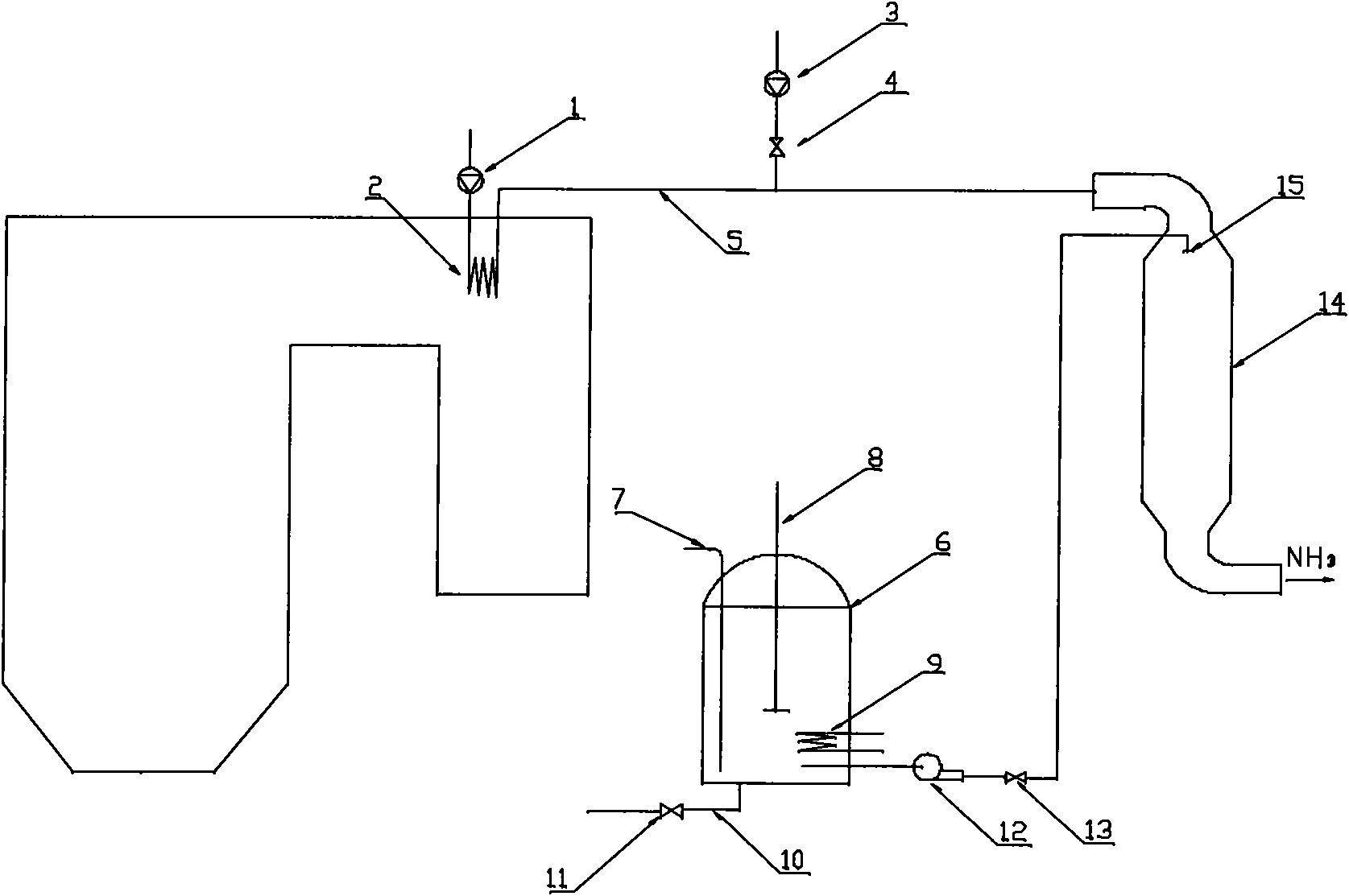
[0030] figure 1 Shown is the schematic diagram of the system used in the urea ammonia production process for boiler flue gas denitrification of the present invention, including: a urea solution supply system, a heat source system and a decomposition chamber connected to the urea solution supply system and the heat source system through pipelines respectively 14.

[0031] Wherein, the urea solution supply system includes a storage tank 6, a feeding pipe 7 inserted into the storage tank 6 from the top of the storage tank 6, an agitator 8 and a heater 9 arranged inside the storage tank 6, The blowdown pipeline 10 that is arranged at the bottom of the storage tank 6 and the blowdown valve 11 connected with the blowdown pipeline 10, and the feed pump 12 that is arranged on the pipeline that is used to connect the storage tank 6 and the decomposition chamber 14 and outlet valve 13.

[0032] The top of the decomposition chamber 14 is provided with a nozzle 15 .

[0033] The heat s...


PUM


Abstract

The invention discloses a process for producing ammonia from urea used for denitration of boiler smoke and a system thereof. The process has the following flow: feeding a urea solution into a decomposition chamber by a urea solution feeding system; and heating and decomposing the urea solution into ammonia in the decomposition chamber, wherein a heat source for heating the urea solution in the decomposition chamber is air heated by heat in a boiler. The invention adopts the heat in the boiler as the heat source instead of traditional diesel and gas fuel, thus saving the energy resources, greatly lowering the operation cost and improving the system economy, and the process in the invention has safer and more reliable operation compared with the process utilizing fuels such as diesel, gas and the like as the heat source.

Description

technical field [0001] The invention belongs to the field of flue gas denitrification, and in particular relates to a process for producing ammonia from urea for boiler flue gas denitrification and a system thereof. Background technique [0002] With nitrogen oxides (NO x ) emission pollution is becoming more and more serious, and the way to control nitrogen oxides has become a hot environmental issue of current social concern. [0003] In commonly used removal of NO x Among the methods, selective catalytic reduction (SCR) has the ability to remove NO x The advantages of high efficiency and less reducing agent consumption have been widely used. The selective catalytic reduction method refers to the use of a reducing agent to selectively react with NO in the flue gas under the action of a catalyst. x A chemical reaction occurs producing harmless nitrogen and water. The reducing agent used is usually ammonia (NH 3 ), but due to the safety hazards in the transportation an...

Claims


Application Information

Patent Timeline
IPC IPC(8): C01C1/08B01D53/90B01D53/56
CPCY02P20/10
Inventor 朱红路
Owner 北京洛卡环保技术有限公司
Why Eureka
Try Eureka