
Microorganism continuous culture device

A technology for culturing devices and microorganisms, which is applied in enzymology/microbiology devices, biochemical cleaning devices, biomass post-processing, etc., can solve the problems of limited effective aeration area, decreased aeration efficiency, fluctuation of aeration pore size, etc. Achieve the effect of avoiding uneven feed pressure and overflow speed, increasing the concentration of suspended bacteria and reducing heat loss

Active Publication Date: 2021-01-15
CENT SOUTH UNIV
View PDF11 Cites 1 Cited by
  • Summary
  • Abstract
  • Description
  • Claims
  • Application Information

AI Technical Summary

Problems solved by technology

This aeration method needs to control the specific direction of the air bubbles. If the aeration hole is too large, the air bubbles will be too large, and the aeration efficiency per unit volume will decrease. If the aeration hole is too small, the air bubbles will move along the airflow direction and the path will be short, and will not form a spiral. Stirring, the effective aeration area is limited to the vicinity of the aeration tube
And for the iron oxide leaching microbial culture system, the formed precipitate particles will cause the aeration aperture to fluctuate within a certain range
Therefore, the aeration method in the prior art is difficult to take into account the effects of high-efficiency aeration and reducing scaling of heating pipes (iron-vanadium-like substances that are easily formed under the action of leaching microorganisms tend to be formed on heating) at the same time.

Method used


Image

  • Microorganism continuous culture device
  • Microorganism continuous culture device
  • Microorganism continuous culture device

Examples


Embodiment Construction

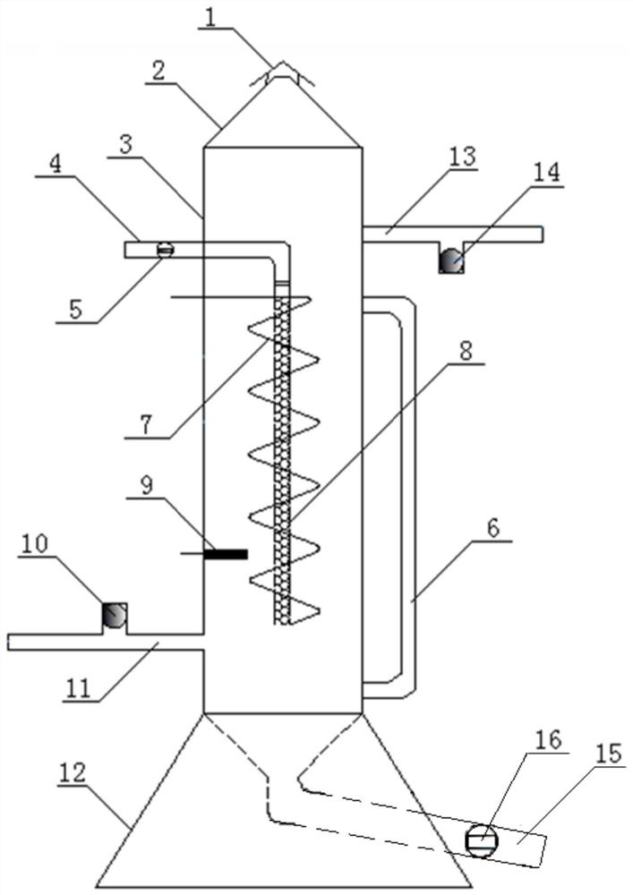
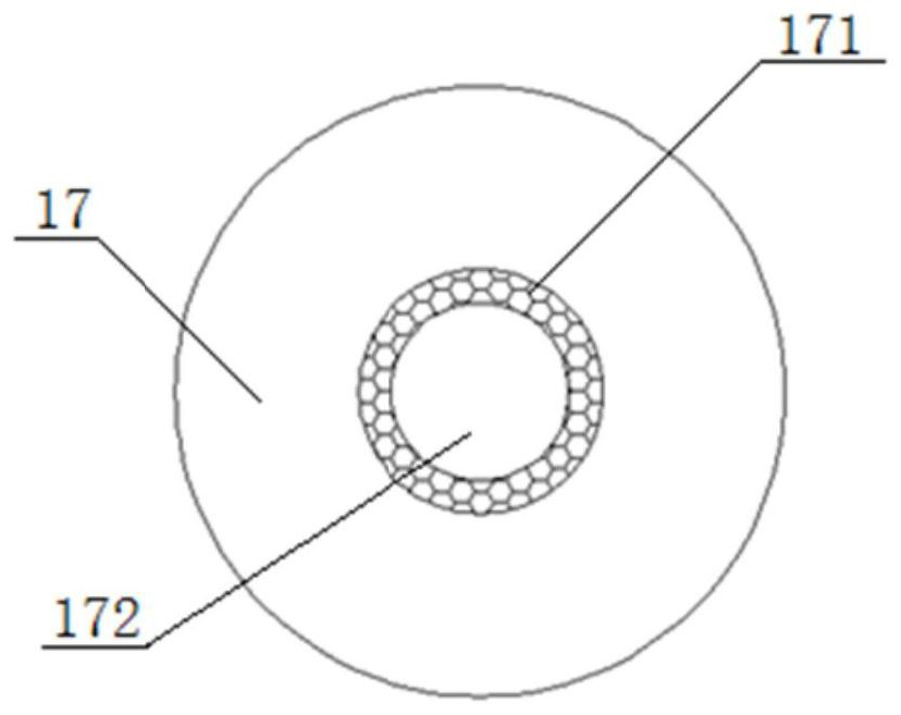
[0034] Such as Figure 2-7 As shown, the present invention includes a culture tank 3 and an aeration tube 8 arranged in the culture tank 3, and also includes a heating tube 7 surrounding the periphery of the aeration tube 8 and heating the culture solution in the culture tank 3, the aeration The tube 8 is also fixed with a plurality of baffles 17 distributed axially along the aeration tube 8. The baffles 17 are circular in shape and the center is sunken downwards. Holes 171 , the heating tube 7 spirals around the periphery of the aeration tube 8 , and the diameter of the spiral is larger than the diameter of the baffle plate 17 .

[0035] The culture tank 3 of the present invention is arranged on the base 12, and the upper base is a circular platform hollow structure, the height of the base is 1 / 5-1 / 6 of the total height of the device, and the radius of the bottom of the base is 1 / 3-1 / 4 of the total height of the device. The discharge pipe 15 is about 1 / 3-1 / 4 of the base heig...


PUM

PropertyMeasurementUnit
pore sizeaaaaaaaaaa
thicknessaaaaaaaaaa
thicknessaaaaaaaaaa

Abstract

The invention belongs to the field of microorganism culture devices, and particularly relates to a microorganism continuous culture device. The device comprises a culture tank and an aeration pipe arranged in the culture tank, and further comprises a heating pipe which surrounds the periphery of the aeration pipe and is used for heating a culture solution in the culture tank. A plurality of baffles distributed in the axial direction of the aeration pipe are further fixed to the aeration pipe, the baffles are annular, the centers of the baffles are sunken downwards, and leaking holes are formedin the positions close to the aeration pipe, of the baffles. The heating pipe spirally surrounds the periphery of the aeration pipe, and the spiral diameter is larger than that of each baffle. The microorganism continuous culture device is simple in structure, convenient to operate and low in manufacturing cost, iron and vanadium attached and deposited on the heating pipe and the culture tank canbe greatly reduced while ore leaching microorganisms are continuously cultured, so that the purpose of continuously obtaining the microorganisms for a long time is achieved, and the service life of the heating device is greatly prolonged.

Description

technical field [0001] The invention belongs to the field of microorganism cultivation devices, and in particular relates to a microorganism continuous cultivation device. Background technique [0002] Biometallurgy is a hydrometallurgical technology that uses ore leaching microorganisms to leach low-grade, highly complex, refractory mineral resources or solid waste containing heavy metals. It has a wide range of metal leaching, good leaching effects, and no pollution. Environmental pressure It is small, and has the advantages of low input cost and good economic benefits, so it is widely used in the field of mining of mineral resources and recovery of secondary resources. [0003] Bioleaching microorganisms play the main role in biometallurgy, so cultivating ore leaching microorganisms and continuously obtaining a large number of leaching microorganisms in the biometallurgy process are the key to ensure bioleaching. In the process of bioleaching process exploration and opti...

Claims


Application Information

Patent Timeline
Patent Type & Authority Applications(China)
IPC IPC(8): C12M1/34C12M1/04C12M1/02C12M1/00
CPCC12M23/38C12M23/48C12M27/20C12M29/06C12M29/20C12M29/26C12M37/04C12M41/44C12M41/12C12M41/00
Inventor 周洪波孙见行王玉光周文博程海娜
Owner CENT SOUTH UNIV
Learn More