Seeding guidance die for growing silicon crystal by directional solidification method

A technology for growing silicon crystals and directional solidification, which is applied in self-solidification, crystal growth, single crystal growth, etc., to achieve the effects of easy processing, dislocation elimination, and low cost

Inactive Publication Date: 2010-12-29
GREENERGY CRYSTAL TECH
View PDF5 Cites 24 Cited by
  • Summary
  • Abstract
  • Description
  • Claims
  • Application Information

AI Technical Summary

Problems solved by technology

[0004] The invention provides a seeding guide mold for growing silicon crystals by directional solidification, which can solve the problem of seed crystal placement without changing the structure of the existing directional

Method used


Image

  • Seeding guidance die for growing silicon crystal by directional solidification method
  • Seeding guidance die for growing silicon crystal by directional solidification method
  • Seeding guidance die for growing silicon crystal by directional solidification method

Examples


Embodiment 1

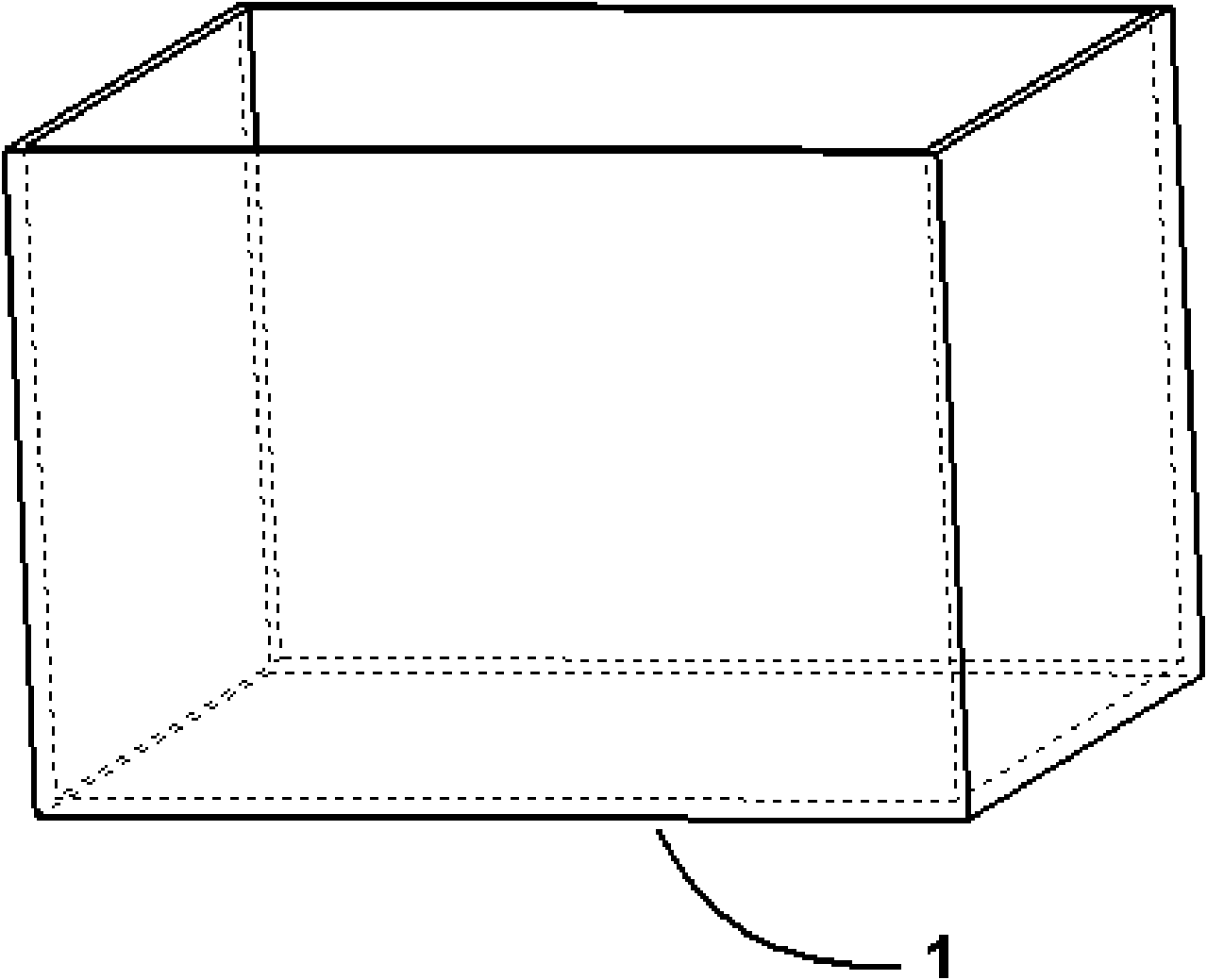
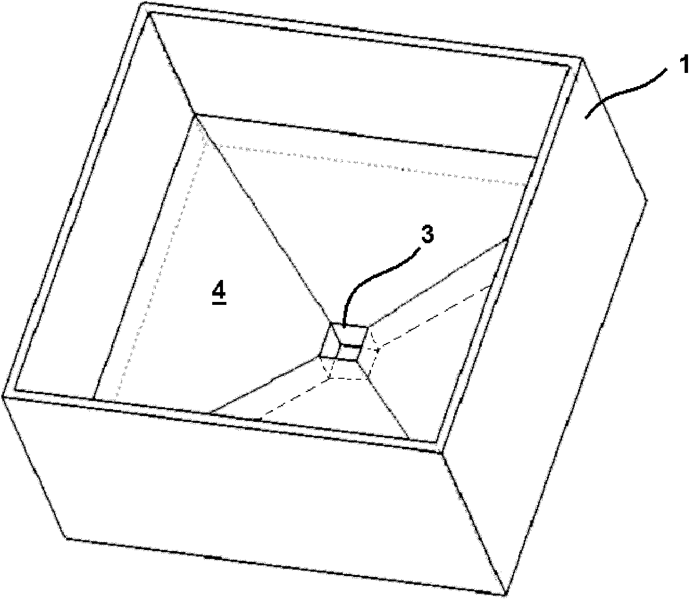
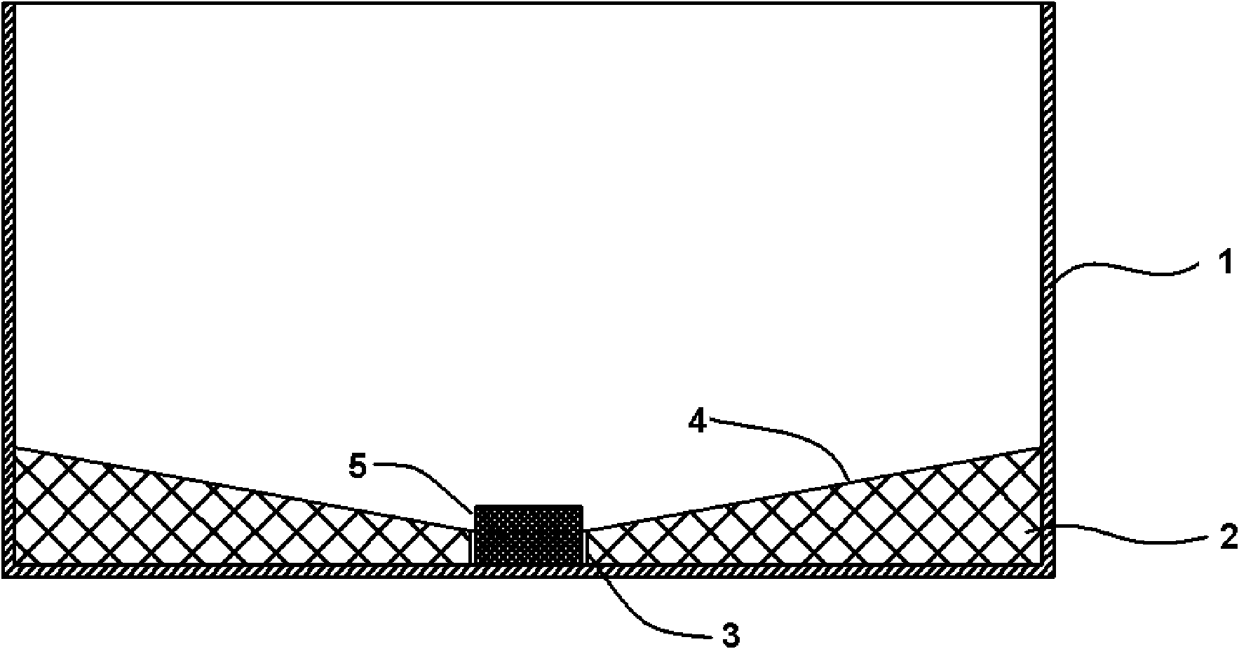
[0028] Such as figure 2 and image 3 A seeding guide mold 2 shown is processed by graphite material and placed on the bottom of the prior art quartz crucible 1, including a seed crystal container 3 and a seed crystal segment 4. There is a square cylinder in the middle of the seed crystal container 3. The first cavity for placing the seed crystal 5, the cross-sectional area of ​​the first cavity is 10000mm 2 , the height is 30mm, and the cross-sectional shape is square; the seeding section 4 is composed of four blocks connected around the seed crystal container 3, and the surface of each block in contact with the silicon raw material placed in the quartz crucible 1 is a slope surface , the bottom of the slope is in contact with the top of the first cavity, the top of the slope is in contact with the side wall of the quartz crucible 1, and the height between the bottom and top of the slope is 15 mm. image 3 A cross-sectional view of the seed guide die is given in .

[0029]...

Embodiment 2

[0033] Such as Figure 4 As shown, the same method as in Example 1 is adopted, the difference is that in order to better control the temperature gradient for seeding, a cavity is provided inside each block of the seeding segment, so that the position of the seed crystal The temperature difference between the temperature and the temperature around the crucible is larger, so that when the silicon melt is kept superheated, the temperature at the seed crystal is just around the melting point.

Embodiment 3

[0035] Such as Figure 5 As shown, the same method as in Example 2 is adopted, the difference is that in order to better seed the crystal and eliminate dislocations, the shape of the seed crystal container 3 of the seeding guide mold 2 is adjusted, that is, the shape of the seed crystal container 3 A cavity near its top part has a diameter contracted to form a 10mm long neck section, the neck section itself is equal in diameter, but because the neck section has a gradually shrinking diameter, the seed crystal grows through the neck section Dislocations growing from the seed crystal are better eliminated when the channel is elongated.


PUM


Abstract

The invention discloses a seeding guidance die for growing crystal by a directional solidification method, which is arranged at the bottom of a quartz crucible and comprises a seed container and a seeding section, wherein the seed container is provided with a first cavity for placing the seeds; the seeding section is composed of one or a plurality of blocks connected around the seed container; the contact surface of the block and a silicon raw material in the quartz crucible is a dome; the dome is bent to form an approximate trapezoid conical surface of which the bottom contacts with the top end of the first cavity; and the top of the trapezoid cone contacts with the side wall of the quartz crucible. The invention can solve the seed placement problem without changing the structure of the existing directional solidification furnace and the quartz crucible, and eliminates seed dislocation in the seeding process so as to effectively grow monocrystalline silicon or polycrystalline silicon ingots with large crystal grains. The seeding guidance die of the invention has low cost and easy manufacture.

Description

technical field [0001] The present invention relates to a kind of equipment for manufacturing silicon single crystal, especially a kind of mold used for silicon crystal seeding guide in the thermal field of growing silicon single crystal by directional solidification method, that is, the mold used for growing silicon crystal by directional solidification method Seeding guide mold in a quartz crucible. Background technique [0002] Silicon single crystal and silicon polycrystalline ingot are the most commonly used materials for crystalline silicon solar cells. Generally, solar cells manufactured using silicon single crystal materials have higher photoelectric conversion efficiency than solar cells manufactured using silicon polycrystalline materials. At present, the most commonly used manufacturing methods for silicon single crystal are pulling method (Czochralski method) and zone melting method (Floating Zone method); the manufacturing method for silicon polycrystal usually...

Claims


Application Information

Patent Timeline
IPC IPC(8): C30B11/00C30B29/06
Inventor 李乔马远
Owner GREENERGY CRYSTAL TECH
Why Eureka
Try Eureka