Coaxial composite welding method of laser spot welding and resistance spot welding

A technology of resistance spot welding and hybrid welding, applied in laser welding equipment, welding equipment, metal processing equipment, etc., can solve problems such as poor welding performance, improve mechanical properties, delay cooling rate, improve absorption rate and welding stability sexual effect

Inactive Publication Date: 2011-01-05
HARBIN INST OF TECH
View PDF6 Cites 11 Cited by
  • Summary
  • Abstract
  • Description
  • Claims
  • Application Information

AI Technical Summary

Problems solved by technology

[0004] The purpose of the present invention is to solve the problem of poor solder joint performance when the laser spot welding process is applied to aluminum alloy materials, and to provide a coaxial composite welding method of laser and resistance spot welding

Method used


Image

  • Coaxial composite welding method of laser spot welding and resistance spot welding
  • Coaxial composite welding method of laser spot welding and resistance spot welding
  • Coaxial composite welding method of laser spot welding and resistance spot welding

Examples


specific Embodiment approach 1

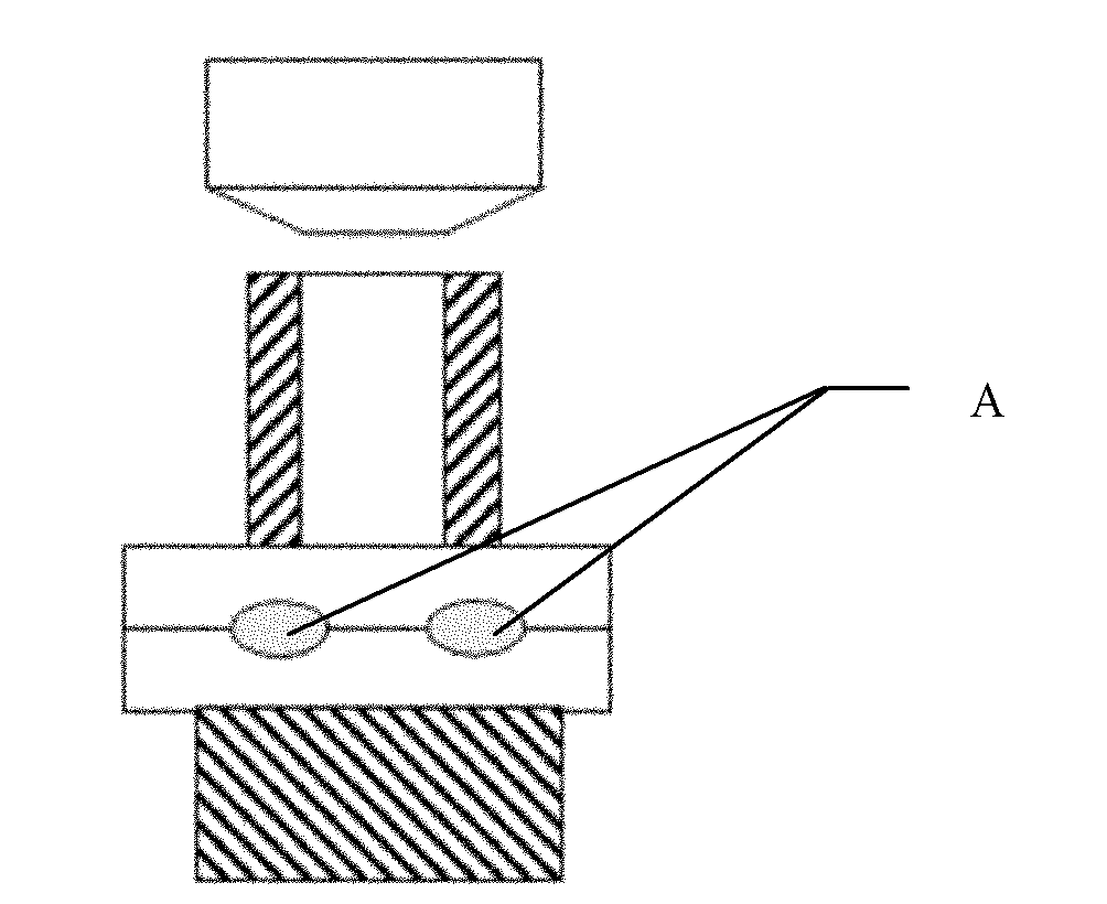
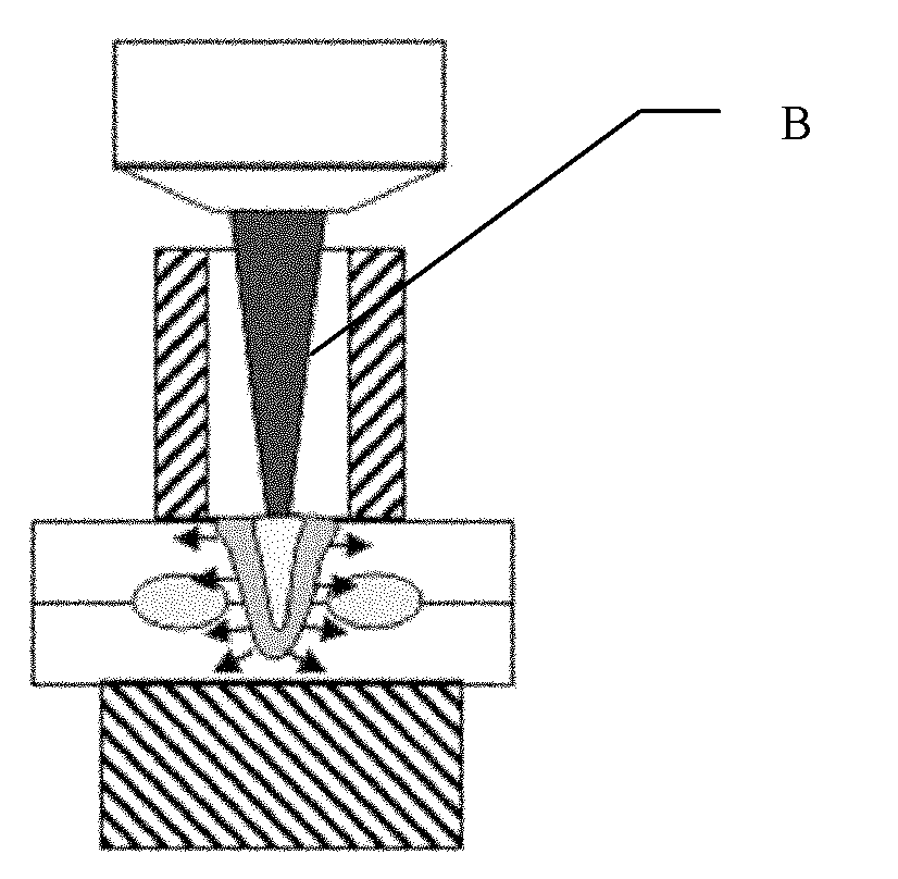
[0017] Specific implementation mode one: the following combination Figure 1 to Figure 5 Describe this embodiment, the welding method described in this embodiment is based on the existing method of resistance spot welding of the base metal to be welded, the upper electrode in the resistance spot welding method adopts a hollow electrode, and the resistance spot welding of the base material to be welded At the same time, the laser beam passes through the center of the hollow electrode to perform laser spot welding on the base material to be welded, so as to realize the coaxial combination of laser spot welding and resistance spot welding.

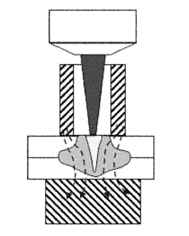
[0018] Laser spot welding forms a welding pool and a keyhole on the base metal to be welded, and connects with the molten pool formed by resistance spot welding, finally forming a cross-shaped welding spot.

[0019] The lower electrode in the resistance spot welding method in this embodiment is in the form of an electrode used in a convention...

specific Embodiment approach 2

[0024] Embodiment 2: This embodiment is a further limitation of Embodiment 1. The outer diameter of the hollow electrode is 13 mm to 30 mm, the inner diameter of the hollow electrode is 3 mm to 15 mm, and the wall thickness of the hollow electrode is greater than or equal to 5mm.

[0025] If the outer diameter of the hollow electrode is too small, the electrode will be easily deformed during the resistance spot welding process, and satisfactory weld formation cannot be obtained; if the inner diameter of the hollow electrode is too small, the laser beam will not pass through.

specific Embodiment approach 3

[0026] Specific embodiment three: this embodiment is a further limitation to embodiment one or two, the welding duration of the welding method is 0.06s to 0.5s, the welding current of resistance spot welding is 2000A to 12000A, the welding of laser spot welding The power is from 100W to 5000W.

[0027] In the laser-resistance spot welding coaxial composite welding process, if the laser power is too large, the heat generated by the laser energy and the plasma radiation generated by the laser welding to the electrode will easily cause the electrode to deform.


PUM

PropertyMeasurementUnit
thicknessaaaaaaaaaa

Abstract

The invention discloses a coaxial composite welding method of laser spot welding and resistance spot welding, belonging to the technical field of welding. The method solves the problem of poor welding spot performance when the laser spot welding technology is,applied to an aluminum alloy material. The welding method of the invention is based on the existing resistance spot welding method of the base material to be welded. A top electrode in the laser spot welding method uses a hollow electrode. When performing the resistance spot welding on the base material to be welded, a laser beam passes through the center of the hollow electrode to perform the laser spot welding on the base material to be welded, so as to realize the coaxial composite of the laser spot welding and the resistance spot welding. The method of the invention is used as a welding technology.

Description

technical field [0001] The invention relates to a coaxial composite welding method of laser and resistance spot welding, which belongs to the field of welding technology. Background technique [0002] In recent years, laser manufacturing technology has developed by leaps and bounds. The famous A380 Airbus uses laser welding technology instead of traditional riveting technology to connect the fuselage of the new aluminum alloy composite material in the manufacturing process. Because of its strong adaptability to materials and structures, it has great development potential no matter in aerospace, national defense or civil industry. [0003] Based on this background, laser spot welding technology has begun to emerge in the automobile manufacturing industry. It has obvious advantages in terms of solder joint performance, welding efficiency and welding cost for steel material structures. However, for aluminum alloy materials with high reflectivity, there are still big problems i...

Claims


Application Information

Patent Timeline
Patent Type & Authority Applications(China)
IPC IPC(8): B23K28/02B23K26/346
Inventor 陈彦宾李俐群雷正龙
Owner HARBIN INST OF TECH
Why Eureka
Try Eureka