Device for automatically testing performance of cable bunch

An automatic test device and cable harness technology, applied in the direction of measuring devices, measuring electricity, measuring electrical variables, etc., can solve problems such as poor contact, low efficiency, and failure to detect

Inactive Publication Date: 2011-01-05
HARBIN JIANCHENG GRP
View PDF0 Cites 35 Cited by
  • Summary
  • Abstract
  • Description
  • Claims
  • Application Information

AI Technical Summary

Problems solved by technology

[0004] In order to solve the problems of low efficiency and inability to detect wrong connection, multi-connection and poor contact i

Method used


Image

  • Device for automatically testing performance of cable bunch
  • Device for automatically testing performance of cable bunch
  • Device for automatically testing performance of cable bunch

Examples


specific Embodiment approach 1

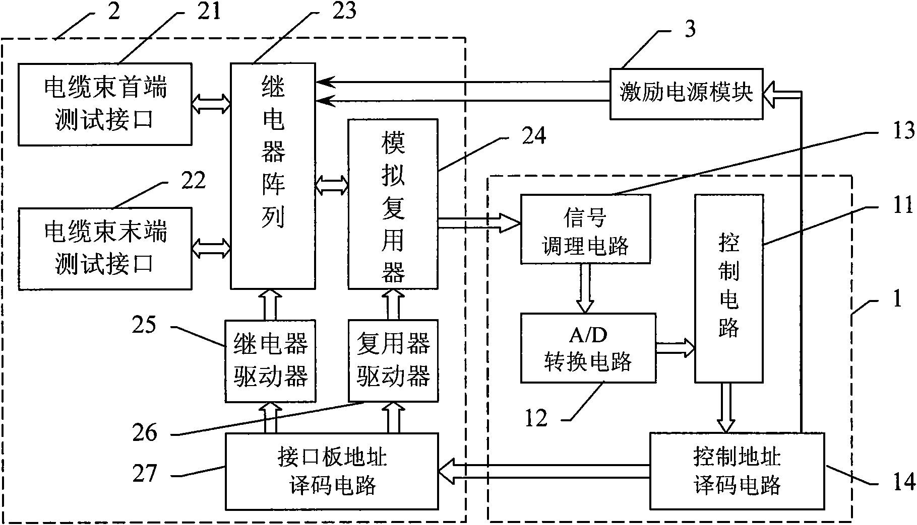
[0008] Specific implementation mode one: see figure 1 This embodiment will be described. The cable harness performance automatic test device described in this embodiment includes an excitation power supply module 3, a control measurement board 1 and a measurement interface board 2,

[0009] The control interface board includes a control circuit 11, a signal conditioning circuit 13, an A / D conversion circuit 12 and a control address decoding circuit 14, and the measurement address selection signal output terminal of the control circuit 11 is connected to the address selection signal input terminal of the control address decoding circuit 14 , the power control signal output end of the control circuit 11 is connected to the control signal input end of the excitation power module 3, and the two excitation power signal output ends of the excitation power module 3 are connected to the two excitation power signal input ends of the test interface board, A / D conversion The analog sign...

specific Embodiment approach 2

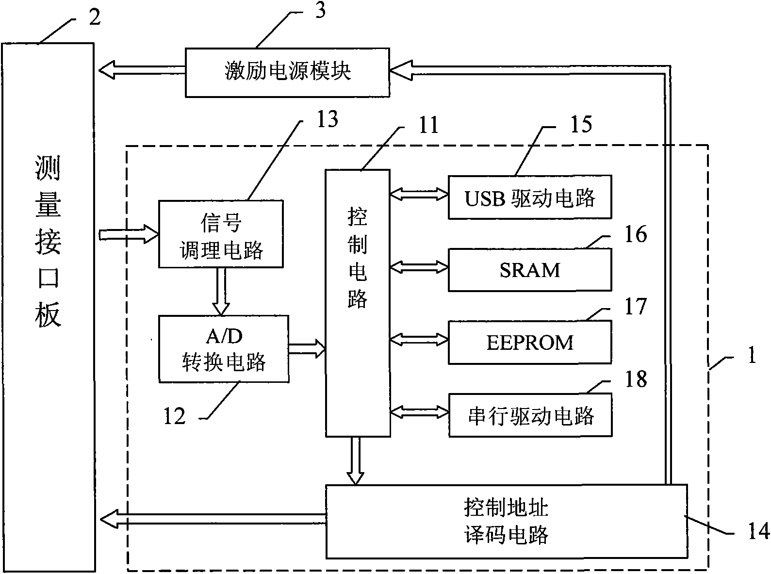
[0032] Specific embodiment two: The cable harness performance automatic testing device described in this embodiment is based on the technical solution described in specific embodiment one, and a serial drive circuit 18 is added, and the data of the serial drive circuit 18 The serial input / output terminal is connected to the serial data input / output terminal of the control circuit 11 .

[0033] The serial driving circuit 18 added in this embodiment can be realized by using an existing SPI communication driving circuit. After the serial driving circuit 18 is added, the cascade operation of multiple cable harness performance automatic testing devices can be realized.

[0034] In order to increase the communication speed and simplify the design, the synchronous serial peripheral interface SPI of the single-chip microcomputer C8051 is adopted in this embodiment, which provides a communication speed exceeding 2Mbps. The single-chip microcomputer SPI interface of the main test devic...

specific Embodiment approach 3

[0036] Specific embodiment three: The cable harness performance automatic test device described in this embodiment is based on the technical solution described in specific embodiment one or two, and a USB drive circuit 15 is added, and the serial number of the USB drive circuit 15 The row data input / output terminal is connected to the serial control data input / output terminal of the control circuit 11 .

[0037] The USB drive circuit 15 added in this embodiment can realize the communication function between the test device and the host computer. During the measurement process, the measured data obtained by the measurement is reported to the upper computer in real time through the USB drive circuit 15 . Described USB drive circuit 15 can adopt the device PDIUSBD12 type integrated circuit of PHILIPS company to be fully compatible with USB1. Just like a piece of RAM device externally expanded by the single-chip microcomputer, the main program is notified to handle the upper comp...


PUM


Abstract

The invention discloses a device for automatically testing the performance of a cable bunch, which relates to a cable bunch performance testing device and solves the problems that the traditional cable bunch performance testing method is inefficient and incapable of detecting misconnection, over-connection and poor contact. A control interface board in the device is used for controlling a measuring interface board to sequentially connect each connector at one end of a cable bunch to be measured and each connector at the other end to two power output ends of an excitation power module respectively, controlling a voltage signal output by the excitation power module and detecting the voltage and the current between two terminals connected to a measuring circuit so as to obtain the resistance value of a lead wire to be measured; a measuring structure board comprises a measuring interface and a relay array and is used for selecting and switching a measured port; and the excitation power module comprises a high-voltage direct-current power supply, a low-voltage direct-current power supply and a constant-current direct-current power supply and is used for providing a power signal for measurement. The device is applicable to the performance testing of a multi-core cable bunch.

Description

technical field [0001] The invention relates to a cable harness performance testing device. Background technique [0002] The cable bundle is an important electrical connection part commonly used in various electrical equipment, responsible for the transmission of power, control signals and various electrical information. Whether each wire in the cable bundle is connected to the connectors at both ends The performance parameters of the cable harness, such as the resistance of the wires, whether each wire is in good contact with the connector probe, etc., all affect the performance of the cable harness, and directly affect the performance and reliability of the entire device and system. [0003] Since different equipment requires different cable bundles, the connection methods of the wires in different cable bundles and the junctions at both ends of the cable bundle are different, the existing detection methods for the quality of the cable bundles are generally detected manua...

Claims


Application Information

Patent Timeline
IPC IPC(8): G01R31/02G01R27/08
Inventor 徐迎莉隋铁君于洋韩旭东唐喜宝姜德龙
Owner HARBIN JIANCHENG GRP
Why Eureka
Try Eureka