
Array plasma antenna with omni-directional scanning function

A technology of plasma antennas and arrays, applied to antennas, antenna arrays, antenna grounding devices, etc., can solve the problems of complex feed phase control of antenna arrays, achieve good controllability of the pattern, avoid complexity, and controllability wide effect

Inactive Publication Date: 2011-01-05
SOUTH CHINA UNIV OF TECH
View PDF4 Cites 14 Cited by
  • Summary
  • Abstract
  • Description
  • Claims
  • Application Information

AI Technical Summary

Problems solved by technology

However, this invention is still based on the principle of phased array, that is, the feed signals of each antenna unit must have a certain phase difference, so the feed phase control of the antenna array is relatively complicated

Method used


Image

  • Array plasma antenna with omni-directional scanning function
  • Array plasma antenna with omni-directional scanning function
  • Array plasma antenna with omni-directional scanning function

Examples


Embodiment Construction

[0022] The present invention will be described in further detail below in conjunction with the accompanying drawings, but the embodiments of the present invention are not limited thereto.

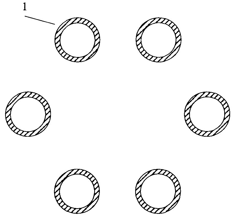
[0023] Such as figure 1 As shown, the omnidirectional scanning plasma antenna array includes a plurality of plasma antenna units 1, and the plurality of plasma antenna units 1 are arranged at equal intervals on the same circular ring, and the distance between two adjacent plasma antenna units 1 Fixed, between λ / 8-λ / 4, where λ=c / f, speed of light c=3×10 8 m / s, f is the working frequency of the plasma antenna array; the number N of plasma antenna elements is 4-8. If the number of antenna elements increases, the linear distance between adjacent antenna elements can be kept constant by increasing the radius of the ring.

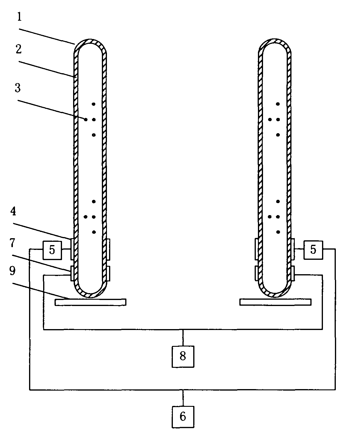
[0024] Such as figure 2 As shown, the plasma antenna unit 1 includes a dielectric tube 2, an inert gas 3, an excitation feed ring 4, a signal feed ring 7 and a ground plat...


PUM

PropertyMeasurementUnit
Thicknessaaaaaaaaaa

Abstract

The invention relates to a plasma antenna array which is constituted by leading a plurality of plasma antenna units to work simultaneously, and the pointing direction of a radiation pattern of the plasma antenna array can carry out omni-directional scanning on the plane on which the plasma antenna units are distributed. Signal feed loops on all the plasma antenna units can feed communication signals with same phase and amplitude onto plasma antennas. The higher exciting power is imposed on the plasma antenna unit in the direction which needs to produce stronger radiation so as to produce plasma with higher density and higher electrical conductivity. A radiation signal of the plasma antenna unit with the higher electrical conductivity is stronger than other antenna units, and then the plasma antenna array can produce the stronger radiation in the desired direction, thereby carrying out the omni-directional scanning on the pattern of the antenna array. The plasma antenna array is characterized in that the plurality of the plasma antennas are arranged into the array and work simultaneously, and the antenna array not only has high gain and directivity, but also has better pattern reconfigurability.

Description

technical field [0001] The invention relates to a plasma antenna array, in particular to an omnidirectional scanning surface wave driven plasma antenna array, which can realize the stealth and reconfigurable functions of the antenna. Background technique [0002] The rapid development of modern mobile communication systems puts forward higher requirements for communication system antennas. Communication antennas are developing towards frequency reconfigurable and pattern reconfigurable. Compared with the traditional metal antenna, the plasma antenna uses plasma instead of ordinary metal to conduct and radiate electromagnetic waves, so it has its unique advantages: First, by controlling the plasma parameters, the radiation pattern, efficiency and working bandwidth of the antenna can be made Realize dynamic reconstruction; second, the plasma antenna is an ordinary medium when it is not excited, and the radar scattering cross section is extremely small. Third, the gas materia...

Claims


Application Information

Patent Timeline
IPC IPC(8): H01Q1/26H01Q1/48H01Q21/00
Inventor 胡斌杰李学识周双
Owner SOUTH CHINA UNIV OF TECH
Learn More