
Heat-dissipation paint for light-emitting diode (LED) lamp

A heat-dissipating coating and LED lamp technology, applied in the field of coatings, can solve the problems of poor temperature resistance and aging resistance, low bonding force of substrates, inconvenient construction, etc., and achieve stable mechanical properties, high bonding force, and good heat dissipation effect Effect

Inactive Publication Date: 2011-01-12
JIANGSU UNIV OF SCI & TECH
View PDF2 Cites 22 Cited by
  • Summary
  • Abstract
  • Description
  • Claims
  • Application Information

AI Technical Summary

Problems solved by technology

At present, thermal conductive adhesive is used to solve the heat dissipation problem of LED lamps, but the materials used have relatively poor temperature resistance and aging resistance, low adhesion to the substrate, poor heat dissipation effect, and inconvenient construction. It is difficult to meet people's expectations for LED lamps. Cooling Requirements

Method used


Image

  • Heat-dissipation paint for light-emitting diode (LED) lamp
  • Heat-dissipation paint for light-emitting diode (LED) lamp

Examples


Embodiment 1

[0012] 1. Proportion by mass percentage:

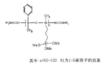
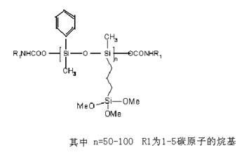
[0013] Silicone polyurethane prepolymer 30%,

[0014] Mixed solvent 20%,

[0015] Silane coupling agent KH560 5%,

[0016] Beryllium Oxide 15%,

[0017] Aluminum nitride, 29%,

[0018] Oleic Acid 1%.

[0019] 2. Preparation method:

[0020] Mix silicone-modified polyurethane prepolymer, mixed solvent, silane coupling agent KH%560, beryllium oxide, aluminum nitride and oleic acid and stir evenly in the reactor, grind to 5-10μm; stop grinding, pack .

[0021] During construction, spray heat-dissipating paint and dry at 200 degrees for 1 hour to form a film and make a 25-50 μm LE heat-dissipating coating.

[0022] Three, embodiment effect:

[0023] Artificial accelerated aging test under 80℃ and 300W ultraviolet irradiation conditions, the aging resistance time is 4800 hours, the temperature resistance is 250 degrees, the bonding shear force is 16MPa., and the thermal conductivity is 250W / (m·K).

Embodiment 2

[0025] 1. Proportion by mass percentage:

[0026] Silicone polyurethane prepolymer 50%,

[0027] Mixed solvent 10%,

[0028] Silane coupling agent KH560 1%,

[0029] Beryllium Oxide 10%,

[0030] Aluminum nitride, 24%,

[0031] Oleic Acid 5%.

[0032] 2. Preparation method:

[0033] The preparation method is the same as in Example 1.

[0034] Three, the effect of this embodiment:

[0035] Artificial accelerated aging test under 80°C and 300W ultraviolet irradiation conditions, the aging resistance time is 4800 hours, the high temperature resistance is 250 degrees, the bonding shear force is 19MPa., and the thermal conductivity is 268W / (m·K).

[0036]

Embodiment 3

[0038] 1. Proportion by mass percentage:

[0039] Silicone polyurethane prepolymer 40%,

[0040] Mixed solvent 10%,

[0041] Silane coupling agent KH560 2%,

[0042] Beryllium Oxide 9%,

[0043] Aluminum nitride, 38%,

[0044] Oleic Acid 1%.

[0045] 2. Preparation method:

[0046] The preparation method is the same as in Example 1.

[0047] Three, the effect of this embodiment:

[0048] Artificial accelerated aging test under 80°C and 300W ultraviolet irradiation conditions, the aging resistance time is 4850 hours, the high temperature resistance is 250 degrees, the bonding shear force is 20MPa., and the thermal conductivity is 290W / (m·K).


PUM

PropertyMeasurementUnit
Bond shearaaaaaaaaaa
Thermal conductivityaaaaaaaaaa
Bond shearaaaaaaaaaa

Abstract

The invention discloses heat-dissipation paint for an LED lamp, which is characterized by comprising the following components in percentage by mass: 30 to 50 percent of organosilicon polyurethane prepolymer, 10 to 20 percent of mixed solvent, 1 to 5 percent of silane coupling agent KH560, 8 to 15 percent of beryllium oxide, 15 to 50 percent of aluminium nitride and 1 to 5 percent of oleinic acid. A preparation method comprises the following steps of: firstly, uniformly blending the liquid components; secondly, adding solid components and uniformly stirring; and finally, grinding on a grinder and then packaging. The heat-dissipation paint for the LED lamp in the invention has the advantages of temperature resistance, aging resistance, high adhesion and good heat-dissipation effect.

Description

technical field [0001] The invention belongs to the technical field of coatings, and relates to a heat dissipation coating, more specifically, to a heat dissipation coating for LED lamps. Background technique [0002] With the rapid expansion of the use range of LED lamps, prolonging the service life of LED lamps has become an urgent problem to be solved. At present, thermal conductive adhesive is used to solve the heat dissipation problem of LED lamps, but the materials used have poor temperature resistance and aging resistance, low adhesion to the base material, poor heat dissipation effect and inconvenient construction. It is difficult to meet people's expectations for LED lamps. cooling requirements. Contents of the invention [0003] The object of the present invention is to solve the above-mentioned problems and overcome the existing defects, and provide a heat-dissipating coating for LED lamps with high adhesion, aging resistance and high heat dissipation coefficie...

Claims


Application Information

Patent Timeline
IPC IPC(8): C09D175/04C09D7/12C09D5/00F21V29/00F21Y101/02F21V29/87
Inventor 高延敏毛慧文
Owner JIANGSU UNIV OF SCI & TECH
Learn More