Laser cladding nozzle convenient for cooling and manufacturing method thereof

A technology of laser cladding and manufacturing method, applied in manufacturing tools, laser welding equipment, welding equipment, etc., can solve the problems of limited cooling area, water leakage, complicated process, etc., to achieve good powder feeding effect and improve the effect of powder feeding quality.

Inactive Publication Date: 2011-01-12
SOUTH CHINA UNIV OF TECH
View PDF6 Cites 27 Cited by
  • Summary
  • Abstract
  • Description
  • Claims
  • Application Information

AI Technical Summary

Problems solved by technology

[0005] In summary, the existing technologies generally have the following deficiencies: (1) Limited by the processing method, the water cooling jacket needs to be processed separately, and then combined with the nozzle by welding. This method is not only cumbersome, but also It is easy to cause water leakage due to weld quality problems; (2) The cooling area is limited, and the cooling effect on the lower edge of the nozzle that is most affected by heat radiation is not very good; (3) As mentioned earlier, the nozzle is composed of multiple parts The overall structure is complex, and it is easy to affect the powder feeding effect or cause water leakage due to improper assembly and other problems.

Method used


Image

  • Laser cladding nozzle convenient for cooling and manufacturing method thereof
  • Laser cladding nozzle convenient for cooling and manufacturing method thereof
  • Laser cladding nozzle convenient for cooling and manufacturing method thereof

Examples


Embodiment 1

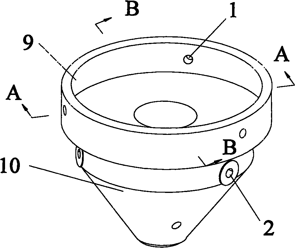
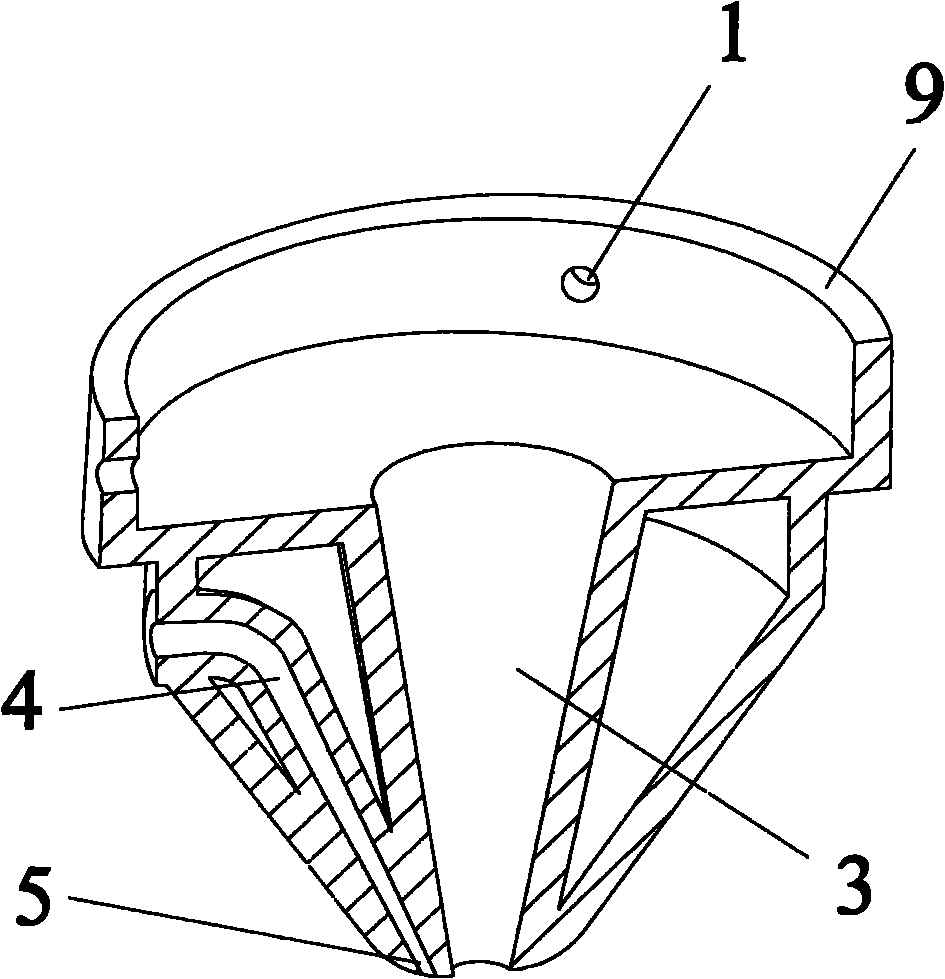
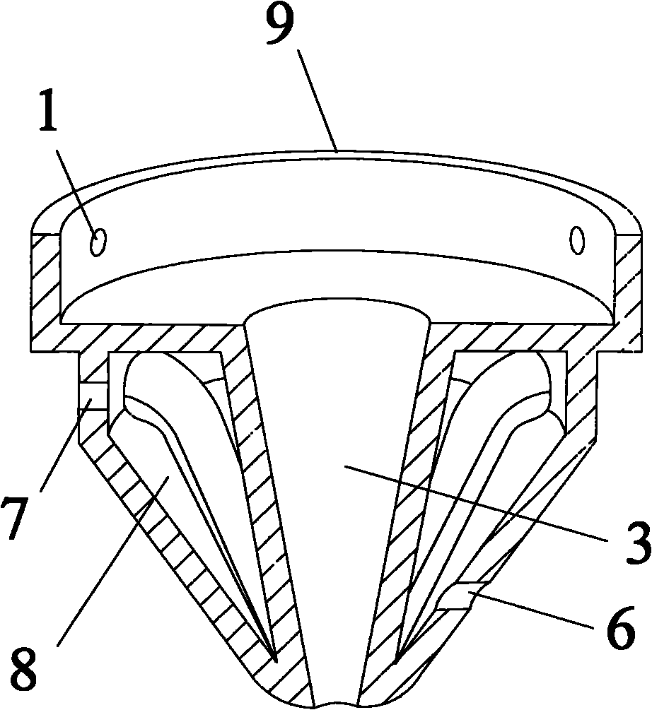
[0038] Such as figure 1 As shown, the laser cladding nozzle that is convenient for cooling includes a nozzle core 10 and a connecting head 9 connected above it for an external laser system. The nozzle core 10 is provided with a beam channel 3, a cooling cavity 8 and three The powder feeding channel 4, the cooling cavity 8 is the cavity formed between the outer circumference of the beam channel 3, the outer circumference of each powder feeding channel 4, and the inner wall of the nozzle core 10 (that is, in the nozzle core 10, the beam channel 3 and the powder feeding channel are removed. The remaining cavity part behind the passage 4 all constitutes the cooling cavity 8); as figure 2 and image 3As shown, the outer wall of the upper end of the nozzle core 10 is provided with a powder inlet 2 communicating with the powder feeding channel 4 and a water outlet 7 communicating with the cooling cavity 8, and the lower end of the nozzle core 10 is opened with a powder feeding chan...

Embodiment 2

[0053] Present embodiment except following feature other structures are with embodiment 1: as Figure 4 As shown, the beam channel 3 is a through hole opened at the center of the nozzle core, and the through hole is a cylindrical hole.

[0054] In the step (3), the raw material powder is copper.

Embodiment 3

[0056] Present embodiment except following feature other structures are with embodiment 1: as Figure 5 As shown, the connecting head is a cylinder provided with an external thread 11, and a through hole 12 communicated with the beam passage is opened at the center thereof.

[0057] The number of powder feeding channels 4 is six; the number of powder inlets 2 and powder outlets 5 is the same as the number of powder feeding channels 4, which are six respectively, and six powder inlets 2 and six powder outlets 5 They are respectively connected with six powder feeding channels 4, and the powder inlet 2, powder outlet 5 and powder feeding channel 4 correspond one by one; the outer wall thickness of the nozzle core is 5 mm; the wall thickness of the beam channel is 5 mm; the powder feeding channel 4 The wall thickness is 5mm.


PUM

PropertyMeasurementUnit
thicknessaaaaaaaaaa
thicknessaaaaaaaaaa

Abstract

The invention discloses a laser cladding nozzle convenient for cooling, comprising a nozzle wick and a connector which is connected above the nozzle wick and is externally connected with a laser system, wherein the nozzle wick is provided with a light beam channel, cooling cavities and a plurality of powder feeding channels; the cooling cavities are formed by the periphery of the light beam channel and the periphery of each powder feeding channel; the outer side wall of the upper end of the nozzle wick is provided with powder inlets communicated with the powder feeding channels and a water outlet communicated with the cooling cavities respectively; the lower end of the nozzle wick is provided with powder outlets communicated with the powder feeding channels and a water inlet communicated with the cooling cavities; and the water inlet and the water outlet are respectively connected with a cooling system externally. The invention also discloses a manufacturing method of the nozzle, comprising the steps of model drawing, slicing treating, rapid forming, after-treatment, etc. The nozzle has simple structure, high cooling effect and better powder feeding quality and is directly manufactured by the rapid forming method, thus design of the nozzle is free from limitation of the traditional processing methods and the structure of the nozzle is further diversified.

Description

technical field [0001] The invention belongs to the technical field of laser processing, and in particular relates to a laser cladding nozzle which is convenient for cooling and a manufacturing method thereof. Background technique [0002] The basic principle of laser cladding technology is: add cladding material on the surface of the substrate, use a laser beam with a certain power density to scan it to completely melt it, and quickly solidify it to form a surface coating that is metallurgically bonded to the substrate. Laser cladding technology has attracted more and more attention due to its advantages of saving strategic metals, protecting the environment, improving the surface properties of materials, and reducing energy consumption. [0003] In the laser cladding system, most of the laser cladding powder feeding systems currently use laser cladding nozzles for powder feeding. The uniformity of powder feeding has a great influence on the cladding quality. The distance ...

Claims


Application Information

Patent Timeline
Patent Type & Authority Applications(China)
IPC IPC(8): C23C24/10B23K26/14B23K26/34
Inventor 杨永强苏旭彬王迪
Owner SOUTH CHINA UNIV OF TECH
Why Eureka
Try Eureka