Measuring analytical system and measuring analytical method for distinguishing diffraction image of particles automatically

An image measurement and analysis system technology, applied in the field of diffraction image measurement and analysis systems, can solve complex and time-consuming processes, biological particles such as cell interference effects, time-consuming and other problems, and achieve the effect of low measurement cost

Inactive Publication Date: 2011-01-12
董珂 +1
View PDF5 Cites 16 Cited by
  • Summary
  • Abstract
  • Description
  • Claims
  • Application Information

AI Technical Summary

Problems solved by technology

However, due to the following reasons, the method of using optical microscopy to analyze and identify particles has limitations and is difficult to use for rapid analysis and identification of particle populations containing a large number of particles
First, commonly used optical microscopes (such as fluorescence microscopes, bright-field or dark-field microscopes, etc.) are designed based on the principle of incoherent imaging, and their images are formed by two-dimensional projection of the three-dimensional structure of particles. The measured particle structure features are structural two-dimensional projection features, which cannot truly reflect the three-dimensional structure and characteristics of particles
Second, since the microscopic image is a two-dimensional projection of the three-dimensional structure of the particle, it usually requires a very complex image analysis method to identify the particle based on the image analysis, especially when analyzing cells with a complex three-dimensional structure, which generally requires manual analysis , so the image analysis method based on the optical microscope is difficult to automate, and the related optical microscope operation and image measurement also need manual operation, which is time-consuming, error-prone and extremely low analysis speed
Third, many particles, including cells, do not contain characteristic absorption or fluorescent molecules in the wavelength range of visible light and near-infrared light, so their structural shapes must be observed under an optical microscope after staining, and staining often requires expensive Reagents and complex and time-consuming procedures, and may have interference effects on the observed biological particles such as cells
Although the above research provides a system and method of how to quickly measure the two-dimensional diffraction image signal of particles in a flowing state, and proves the high correlation between the two-dimensional diffraction image features and the three-dimensional structural features of particles through the particle light scattering model based on classical electrodynamic theory , but extracting the internal three-dimensional structure parameters of a single particle from the diffraction image data distribution through the particle light scattering model and numerical calculation requires a lot of calculations, even on a large computer, it often takes hours or longer to obtain the three-dimensional structure of a single particle Reliable parametric data for large volumes of particles cannot be analyzed
How to measure multiple diffraction images at the same time, and calculate and obtain the image mode characteristics highly correlated with the internal three-dimensional structure of particles, so as to achieve the purpose of fast and accurate analysis and identification of particles, there is no effective system design and analysis method

Method used


Image

  • Measuring analytical system and measuring analytical method for distinguishing diffraction image of particles automatically
  • Measuring analytical system and measuring analytical method for distinguishing diffraction image of particles automatically
  • Measuring analytical system and measuring analytical method for distinguishing diffraction image of particles automatically

Examples


Embodiment Construction

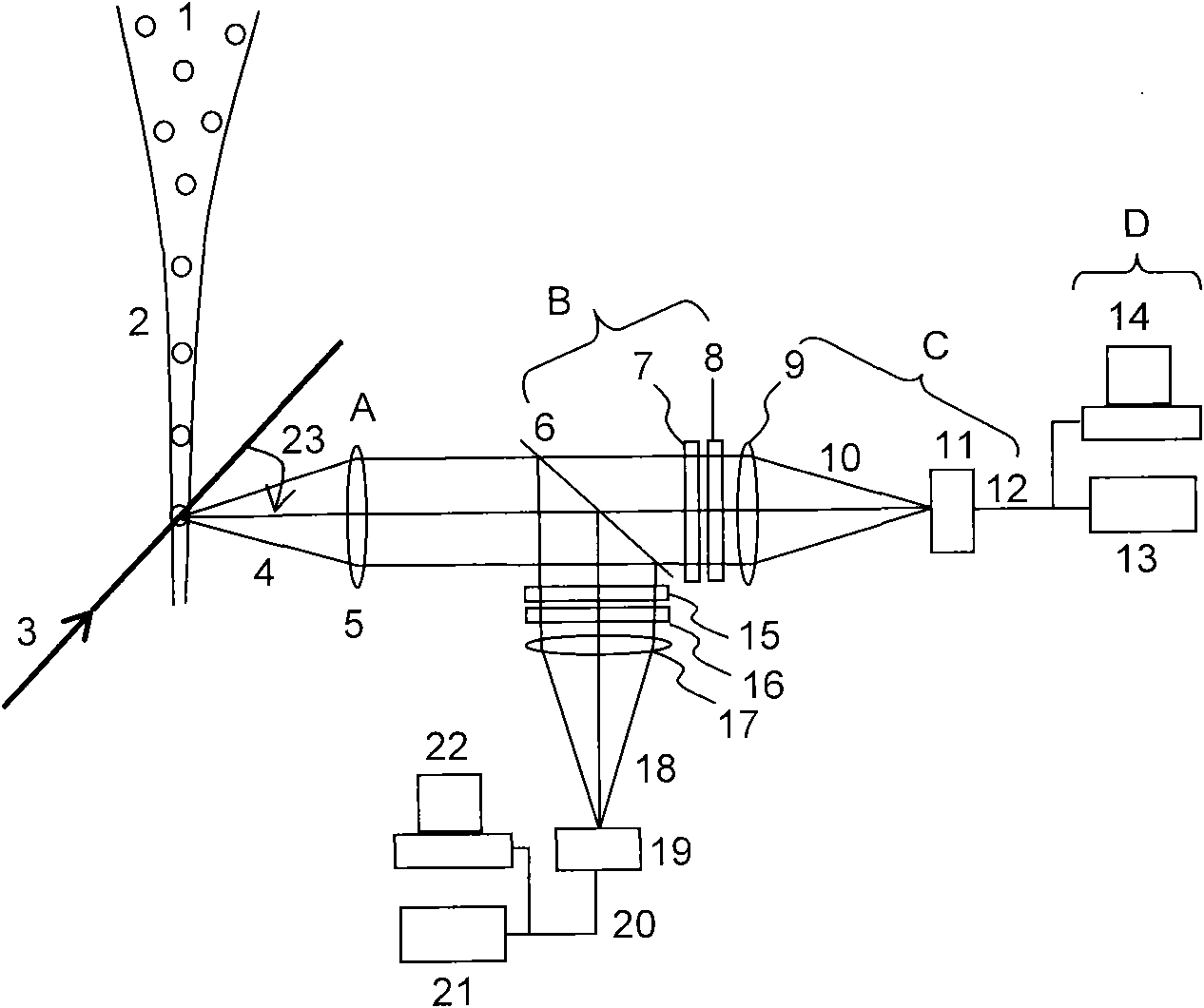
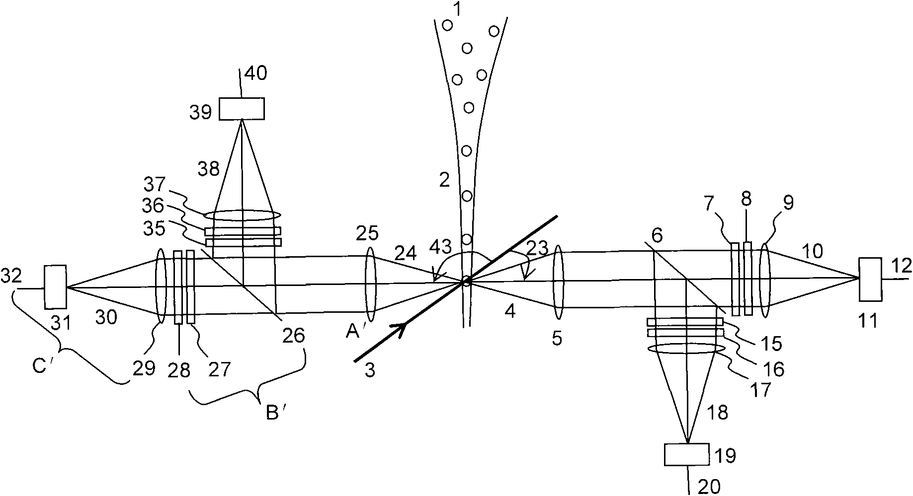
[0066] The diffraction image measurement and analysis system and method for automatically identifying particles of the present invention will be described in detail below in conjunction with the accompanying drawings and embodiments.

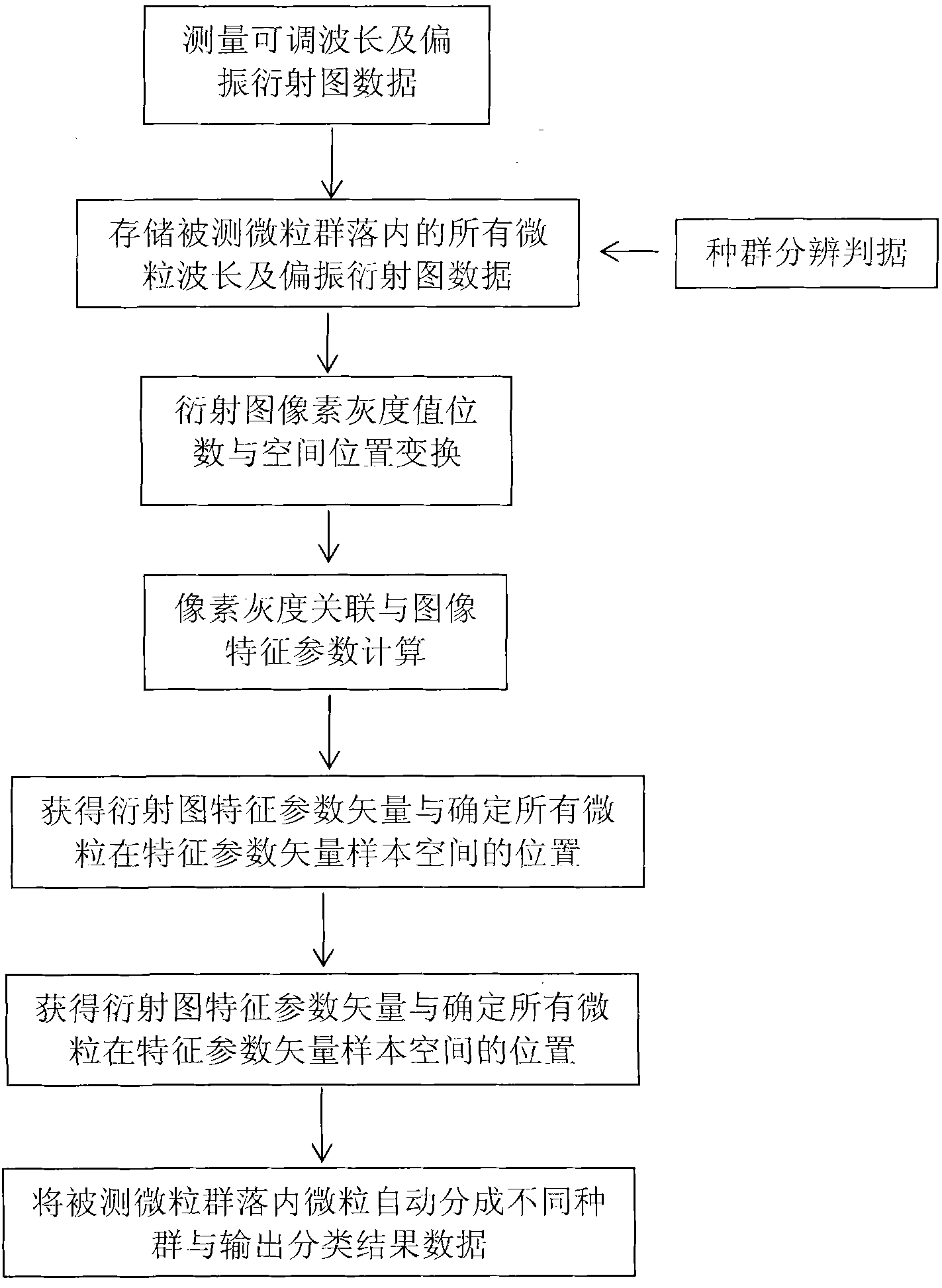
[0067] An implementation method of the diffraction image measurement and analysis system and method for automatically distinguishing particles described in the present invention uses an adjustable imaging system to measure diffraction images of different wavelengths and polarizations, and then quickly analyzes the pixel gray of multiple diffraction image data through computer software. The degree correlation parameters are extracted, and the image pattern statistical parameter vectors are extracted, and the communities containing a large number of particles are quickly classified according to these parameter vectors and population discrimination criteria. The present invention can also be implemented by computer software for rapid population clas...


PUM


Abstract

The invention relates to a measuring analytical system and a measuring analytical method for distinguishing a diffraction image of particles automatically. The system comprises a sample stream formed by flow particles, a coherent excitation light beam intersectant with the sample stream, a first scattered light receiving objective lens part with a first central scattering angle of a coherent scattering light beam, a first light split and filtering part, a first imaging measurement and data output part, an image processing circuit, a computer part and a display part connected with the image processing circuit and the computer part. The method comprises the following steps of: acquiring the corresponding adjustable wavelength and polarizing diffraction image data; storing the data; performing the conversion of image space coordinates; performing characteristic screening and selecting a characteristic area; selecting the characteristic of a diffraction image mode; and determining the position of the measured particles in the characteristic parameter vector sample space of the diffraction image. The measuring analytical system and the measuring analytical method haves the advantage that a large number of particles can be analyzed and distinguished quickly according to the characteristic of a three-dimensional structure in the particles, and the particles are not needed to be dyed.

Description

technical field [0001] The invention relates to a diffraction image measurement and analysis system and method. In particular, it involves measuring the wavelength and polarization-adjustable diffraction image signal formed by the coherent scattering light of particles, calculating and extracting its image features highly correlated with the internal three-dimensional structure characteristics of the particle, and automatically and accurately analyzing and distinguishing particles. Diffraction image measurement and analysis system and method. Background technique [0002] In cell biology research, biotechnology research, drug development, environmental pollution monitoring, atmospheric science and many other fields, researchers need methods and instrument systems that can quickly and accurately analyze and identify a large number of individual particles with a linear scale of one micron to hundreds of microns. In many cases, the functions of particles including biological p...

Claims


Application Information

Patent Timeline
Patent Type & Authority Applications(China)
IPC IPC(8): G01N21/63
Inventor 董珂胡新华
Owner 董珂
Why Eureka
Try Eureka