
Large area fluorescent concentrator solar cell system

A solar cell and large-area technology, applied in the field of solar power generation, can solve the problems of increasing processing costs, difficulty reducing glass thickness, increasing glass size, etc., to reduce material and processing costs, save material and processing costs, reduce double-sided spotlight effect

Inactive Publication Date: 2011-01-19
SHANGHAI DOESUN ENERGY TECH
View PDF5 Cites 15 Cited by
  • Summary
  • Abstract
  • Description
  • Claims
  • Application Information

AI Technical Summary

Problems solved by technology

[0003] 1) Solar cells such as high-efficiency monocrystalline silicon cannot form the best angle with sunlight in urban building curtain walls, which seriously affects the energy conversion efficiency;
[0004] 2) The cost of generating electricity from relatively economical thin-film solar cells such as amorphous silicon used in large-scale power stations is still much higher than that of traditional models
[0007] Concentrating and reflective concentrating technologies have the following disadvantages: a sun tracking device needs to be configured, so the expenditure cost is high, and because all the light in the solar spectrum will be gathered when concentrating, the sunlight outside the effective wavelength range in the solar spectrum The accumulated heat will affect the power generation efficiency and service life of solar cells
[0009] However, the current fluorescent concentrator uses the ratio of the lighting area to the area of ​​the light-emitting side to provide an equivalent light-concentrating effect for the solar cell, so it has the following defects: First, the light-gathering multiple of the lighting area with a diameter of 10 cm is close to the maximum value. To make full use of materials, it is necessary to cut a large-area fluorescent concentrator, which makes it difficult to use the general solar cell packaging process, thereby increasing the processing cost; secondly, the solar cell corresponding to the light-emitting side of the fluorescent concentrator is cut into a width less than 1mm It is also not economical, making it difficult to reduce the thickness of the side of the fluorescent concentrator to less than 1mm, thereby increasing the material cost
For example, a fluorescent concentrator was disclosed in the Massachusetts Institute of Technology in July 2008. This concentrator improved the effect of fluorescent light concentrating because of the use of high-refractive-index glass. Difficulty reducing glass thickness and increasing glass size means the impact on power generation costs is insignificant
Another example is a fluorescent optical fiber solar cell photovoltaic power generation system disclosed in Chinese patent 200810195726.X, which encounters technical difficulties in solar cell coupling due to the too thin diameter of the optical fiber

Method used


Image

  • Large area fluorescent concentrator solar cell system
  • Large area fluorescent concentrator solar cell system
  • Large area fluorescent concentrator solar cell system

Examples


Embodiment Construction

[0032] The embodiments of the present invention will be described in further detail below in conjunction with the accompanying drawings, but the present embodiments are not intended to limit the present invention, and any similar structures and similar changes of the present invention should be included in the protection scope of the present invention.

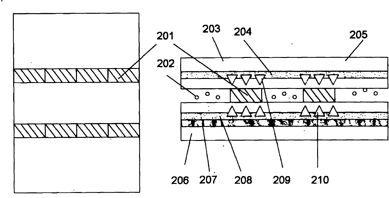
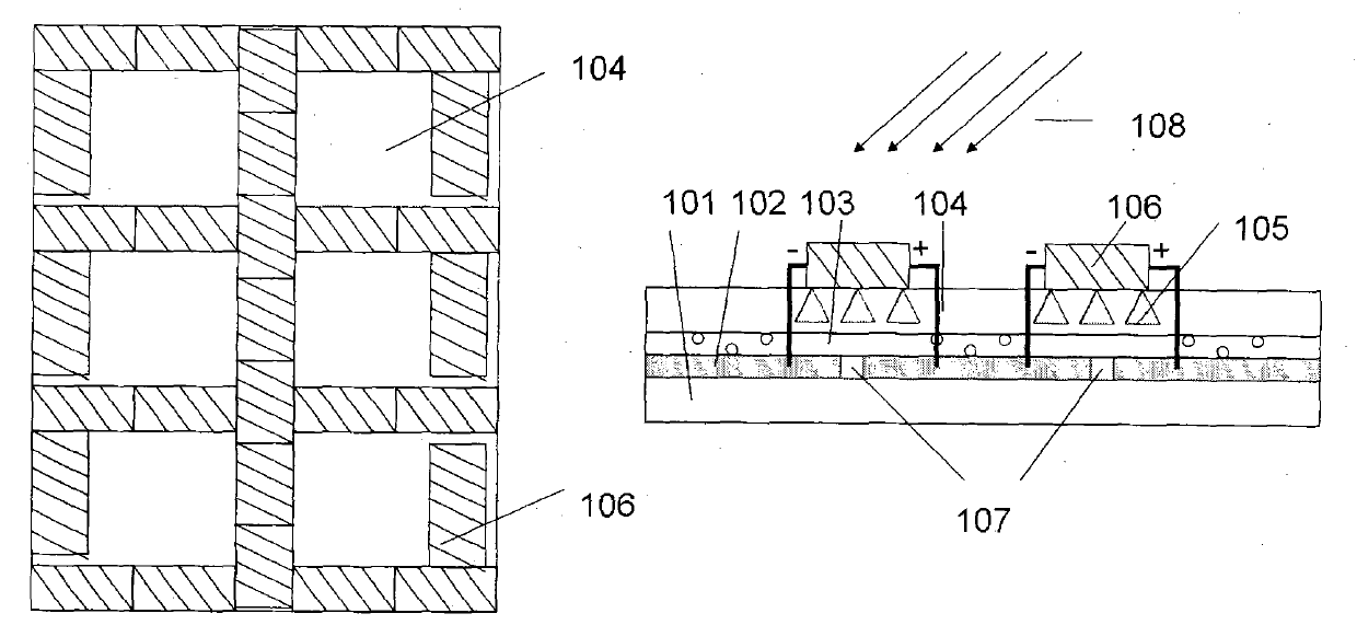
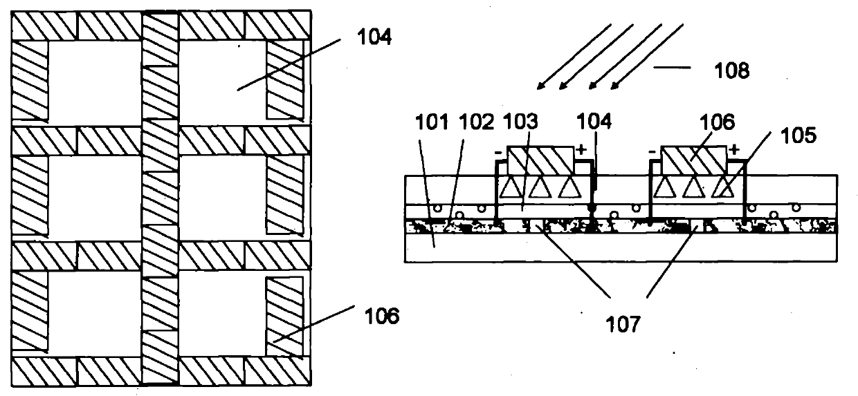
[0033] A large-area fluorescent concentrating solar cell system and its manufacturing method provided by the present invention are characterized in that they include:

[0034] Solar cells with high conversion efficiency such as monocrystalline silicon and their combined light-receiving surfaces are encapsulated on the light guide plate of the fluorescent concentrator by glue;

[0035] One of the fluorescent concentrators is composed of a substrate, containing or not containing a metal reflective layer, a luminescent film and a light-guiding film; the light-guiding plate preferably utilizes a mold with a microstructure formed by...


PUM


Abstract

The invention relates to a large area fluorescent concentrator solar cell system and a manufacturing method thereof, belonging to the technical field of solar power generation and aiming at solving the technical problem of higher generation cost of the traditional solar cell. The generating system comprises at least one fluorescent concentrator comprising or not comprising a reflecting layer, a light guide plate provided with scattering points and formed on a specific area of the fluorescent concentrator, as well as a solar cell installed on the light guide plate and an assembly thereof. The invention has the characteristic that by manufacturing the light guide plate with small light-emitting area on the specific area of the fluorescent concentrator with larger illuminated area so as to provide a light concentration effect for the solar cell in place of the ratio of the illuminated area to the side area of the fluorescent concentrator, the large area fluorescent concentrator solar cell system is obtained under the common solar cell packaging process, and thus, material and processing cost are saved.

Description

technical field [0001] The invention relates to solar power generation technology, in particular to a large-area fluorescent concentrating solar cell system and a manufacturing method thereof. Background technique [0002] The proportion of solar cells in the energy market is increasing, but there are still the following disadvantages: [0003] 1) Solar cells such as high-efficiency monocrystalline silicon cannot form the best angle with sunlight in urban building curtain walls, which seriously affects the energy conversion efficiency; [0004] 2) The cost of generating electricity from relatively economical thin-film solar cells such as amorphous silicon used in large-scale power stations is still much higher than that of traditional models. [0005] Solar concentrating technology has attracted people's attention because it can use relatively cheap materials to increase the power generation of solar cells per unit area. [0006] At present, there are three kinds of solar ...

Claims


Application Information

Patent Timeline
IPC IPC(8): H02N6/00G02B6/00H02S40/22
CPCY02E10/50
Inventor 孙明达王佳孙明柱
Owner SHANGHAI DOESUN ENERGY TECH
Learn More