
Distributed parallel potential acquisition system

A collection system and distributed technology, applied in electrical signal transmission systems, radio wave measurement systems, signal transmission systems, etc., can solve the problems that data points cannot be measured at the same time, measurement results are inaccurate, and there is no economic benefit. Light, convenient construction and low cost

Inactive Publication Date: 2011-01-26
JILIN UNIV
View PDF3 Cites 18 Cited by
  • Summary
  • Abstract
  • Description
  • Claims
  • Application Information

AI Technical Summary

Problems solved by technology

After several decades of secondary oil recovery, the remaining oil is trapped in the sandstone pores in the form of discontinuous oil blocks. At this time, the water content of the produced fluid reaches 85% to 90%, and some even reach 98%. Mining is no longer economical
[0004] At present, the existing measurement instrument systems are all based on single-point potential measurement, that is, the potential is measured point by point around the power supply well, and the distribution range of the remaining oil in the underground reservoir is determined according to the distribution characteristics of the potential. The efficiency is low, and it will inevitably be disturbed by the natural potential that changes with time, resulting in large errors in the measurement results
In recent years, some instruments at home and abroad have also adopted multi-point simultaneous measurement, such as the IPRF-1 developed in Canada and the domestic YL-841 drilling and fracturing fracture azimuth measurement. Data collection is performed in a row mode, and real simultaneous measurement cannot be achieved between data points

Method used


Image

  • Distributed parallel potential acquisition system
  • Distributed parallel potential acquisition system
  • Distributed parallel potential acquisition system

Examples


Embodiment Construction

[0018] Below in conjunction with accompanying drawing and embodiment the present invention is further described in detail:

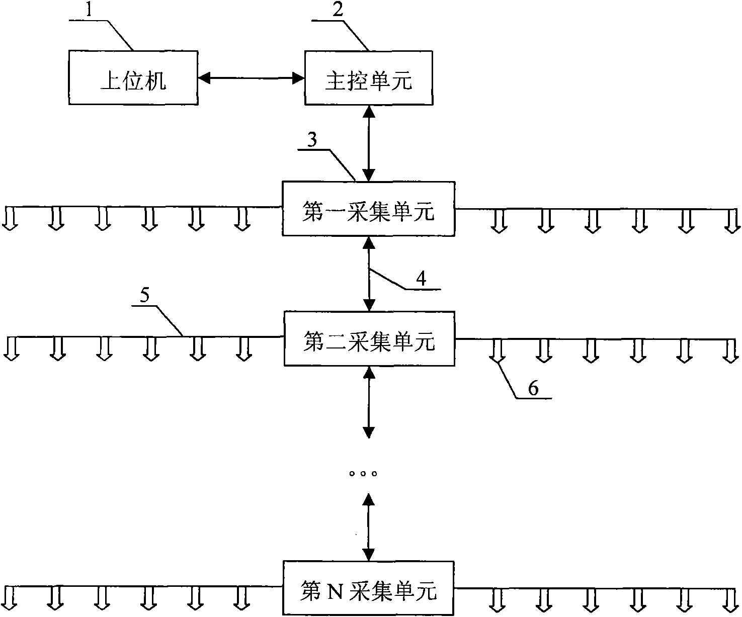
[0019] The distributed parallel ground potential acquisition system is that the host computer 1 is connected to the main control unit 2 through the USB port, and the main control unit 2 is sequentially connected in series with the first acquisition unit, the second acquisition unit, the third acquisition unit and even the third acquisition unit through the data transmission cable 4. N acquisition unit constitutes.

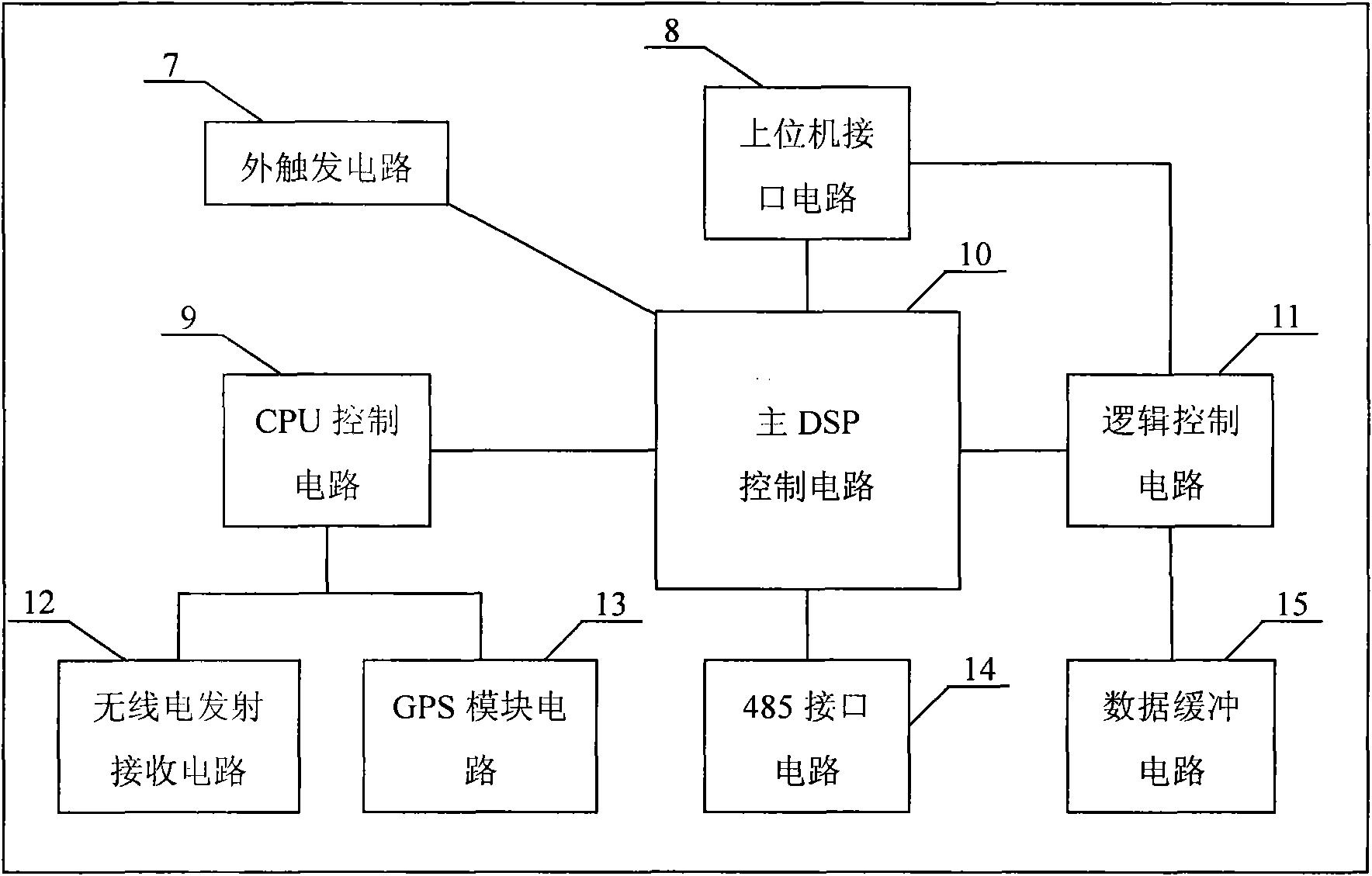
[0020] The main control unit 2 is connected with the external trigger circuit 7, the logic control circuit 11, the 485 interface circuit 14, and the CPU control circuit 9 respectively by the host computer interface circuit 8 through the main DSP control circuit 10, and the host computer interface circuit 8 is connected with the logic control circuit 11 is connected with the data buffer circuit, and the CPU control circuit 9 is connected with ...


PUM


Abstract

The invention relates to a distributed parallel potential acquisition system used for dynamically or statically monitoring residual oil of an oil field, leachate of an refuse dump, and the like by using a potentiometric method, and formed by connecting an upper computer and a main control unit through a USB port and connecting the main control unit, a first acquisition unit, a second acquisition unit, a third acquisition unit and until the N acquisition unit in series sequentially through a data transmission cable. Testing networks of 65535 acquisition units at most can be connected through the data transmission cable. Each acquisition unit has 12 independent measuring channels with high speed and high precision, acquires data by adopting a parallel way and transmits the data in a relay way; the main control unit is designed by adopting a distributed way, the data of the whole testing network can be acquired simultaneously by adopting a digital communication and synchronous technologyamong the acquisition units, and thus the disturbance from a free electric field on the acquired data can be overcome, the induction noise of the whole testing network can be reduced and the whole testing system is simplified. The testing system has the advantages of strong scalability, small size, light weight, low cost and easy construction.

Description

technical field [0001] The invention relates to a geophysical measurement based on the use of a geopotential measurement method to realize dynamic or static monitoring of remaining oil in an oil field, seepage fluid in a garbage dump, etc., especially distributed parallel geopotential data collection. Background technique: [0002] Petroleum is a non-renewable energy, and oil recovery is not only a concern of the petroleum industry, but also the whole society. Oil extraction is divided into three stages. Primary oil recovery relies on formation energy for self-spray production, and its output accounts for about 15% to 20% of the total reserves. After the formation energy is released, artificial water injection or gas injection is used to supplement the energy of the reservoir, so that the crude oil can be continuously extracted, which is called secondary oil recovery. The recovery rate of secondary oil recovery is 15% to 20%. After several decades of secondary oil recover...

Claims


Application Information

Patent Timeline
IPC IPC(8): G01V3/00G08C19/00
Inventor 牛建军张晓培张琪谭笑平
Owner JILIN UNIV
Learn More