
A coil assembly for mr imaging applications

A coil assembly and imaging technology, applied in magnetic resonance measurement, measurement devices, instruments, etc., can solve problems such as inability to install electronic devices

Pending Publication Date: 2022-02-08
SKOPE MAGNETIC RESONANCE TECH AG
View PDF2 Cites 0 Cited by
  • Summary
  • Abstract
  • Description
  • Claims
  • Application Information

AI Technical Summary

Problems solved by technology

Therefore, it cannot be extended and the electronics cannot be mounted outside the RF shield

Method used


Image

  • A coil assembly for mr imaging applications
  • A coil assembly for mr imaging applications
  • A coil assembly for mr imaging applications

Examples


Embodiment Construction

[0073] In general, the same reference numerals will be used for functionally identical or similar features in different drawings, and therefore will not be described more than once unless necessary for understanding the invention.

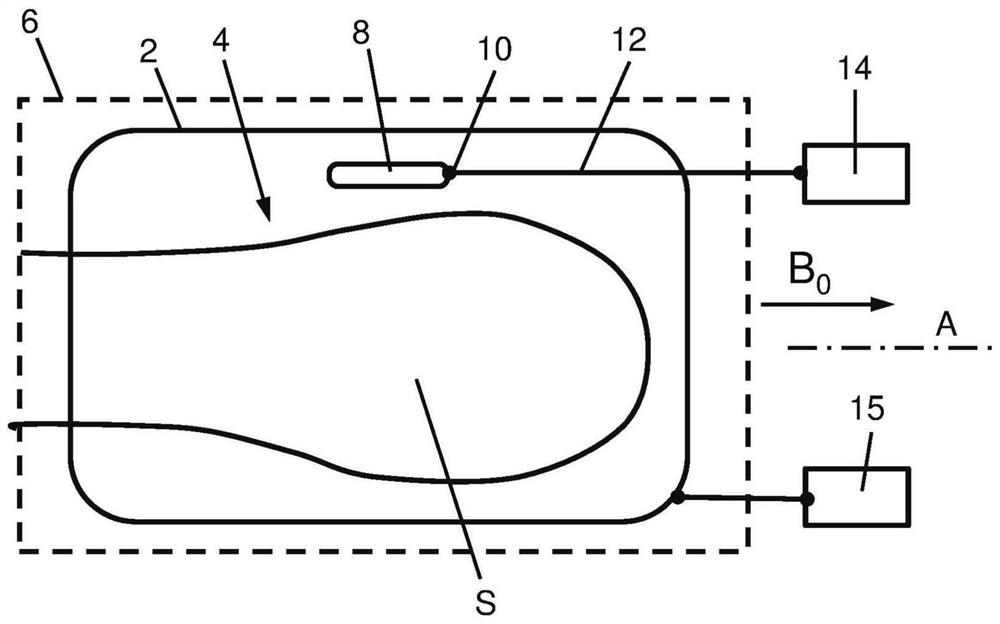
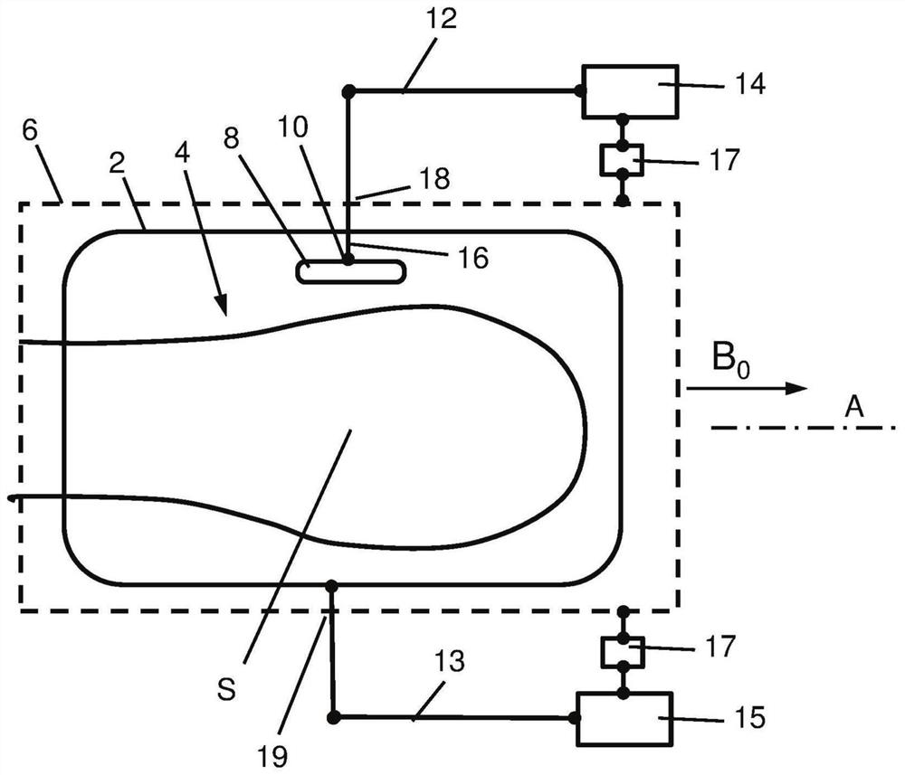
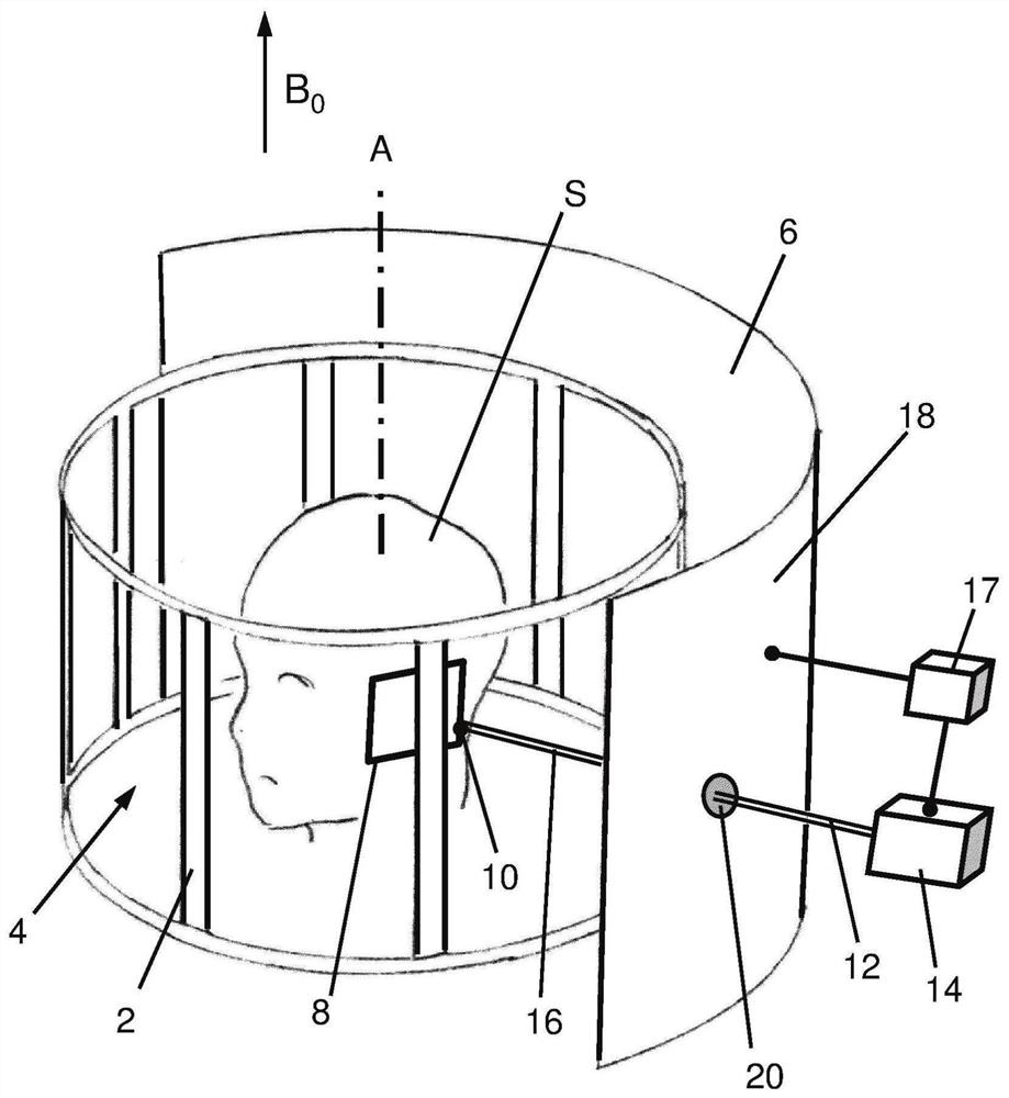
[0074] An apparatus for MR imaging of a subject or object S generally includes an MR device operatively connected to a coil assembly. Such a device according to the prior art is partially shown in FIG. 1 . The coil assembly comprises a conductive RF transmitter coil arrangement 2 for generating an excitation field at the MR operating frequency. The transmitter coil arrangement forms a tubular structure arranged around the imaging volume 4 and having a longitudinal axis A. An outer RF shield 6 (also substantially tubular in the example shown) surrounds the transmitter coil arrangement. The coil assembly also includes a conductive RF receiver coil 8 disposed within the imaging volume for receiving MR signals from a subject or object S disposed with...


PUM


Abstract

A coil assembly for MR imaging applications comprises - an electrically conducting RF transmitter coil arrangement (2) for generating an excitation field at an MR operating frequency, the transmitter coil arrangement forming a tubular structure disposed around an imaging volume (4) and having a longitudinal axis (A); - an external RF shield (6) surrounding the transmitter coil arrangement; - at least one electrically conducting RF receiver coil (8; 8a, 8b) disposed within the imaging volume for receiving MR signal from a subject or object disposed therein, the receiver coil being electrically connected, at a connection point (10; 10a, 10b) thereof, to a respective RF receive line (12; 12a, 12b) connectable to a receiver device (14) located outside of the external RF shield. In order to improve the performance of the coil assembly, the respective RF receive line of each receiver coil is oriented substantially perpendicular to the longitudinal axis (A) in a receiver-proximal segment (16; 16a, 16b) between the connection point (10; 10a, 10b) and a neighboring face portion (18; 18a, 18b) of the external RF shield through which the receive line (12; 12a, 12b) is conducted.

Description

technical field [0001] The present invention generally relates to a coil assembly for magnetic resonance (MR) imaging applications. Background technique [0002] In MR imaging and spectroscopy, magnetic fields are used to process NMR signals. Traditionally, time-varying magnetic gradient fields in multiple directions are superimposed on a constant, uniform main magnetic field to create a spatial modulation of the local magnetic field that penetrates the object under examination. Homogeneous fields are usually produced by superconducting electromagnets. Gradient fields are typically generated by applying a specially shaped current wave to multiple gradient coils. MR excitation is achieved by applying a radio frequency (RF) field at the so-called Larmor frequency according to a predetermined pulse sequence, followed by detection by the RF signal. The acquired RF signal is then converted into image or spectral information by known methods. [0003] According to one mode of ...

Claims


Application Information

Patent Timeline
Patent Type & Authority Applications(China)
IPC IPC(8): G01R33/36G01R33/422G01R33/34G01R33/341G01R33/3415G01R33/58
CPCG01R33/3415G01R33/341G01R33/422G01R33/58G01R33/3685G01R33/34046G01R33/3621G01R33/34076
Inventor D.布鲁纳T.施密德
Owner SKOPE MAGNETIC RESONANCE TECH AG
Learn More