Monitoring method of junction box for photovoltaic module

A photovoltaic module and junction box technology, applied in the field of photovoltaic systems, can solve problems such as single wiring conduction function, cumbersome work, and power generation decline of photovoltaic systems, and achieve the effects of reducing maintenance costs, ensuring economic benefits, and shortening maintenance time

Inactive Publication Date: 2011-01-26
JIANGSU JIUDING SOLAR ENERGY SYST
View PDF7 Cites 18 Cited by
  • Summary
  • Abstract
  • Description
  • Claims
  • Application Information

AI Technical Summary

Problems solved by technology

[0002] At present, the junction boxes used in photovoltaic systems generally only have a single connection function, which cannot reflect the actual working conditions of the connected photovoltaic modules. When a battery in the battery string in the system fails, the current It passes through the diode in the junction box connected in series and parallel with the battery slice. After the diode continues to work, it will generate heat and lose part of the electric energy. Because the diode works under high temperature for a long time, it is very easy to cause damage and short circuit, thus The power generation of the photovoltaic system is

Method used


Image

  • Monitoring method of junction box for photovoltaic module
  • Monitoring method of junction box for photovoltaic module
  • Monitoring method of junction box for photovoltaic module

Examples


Embodiment Construction

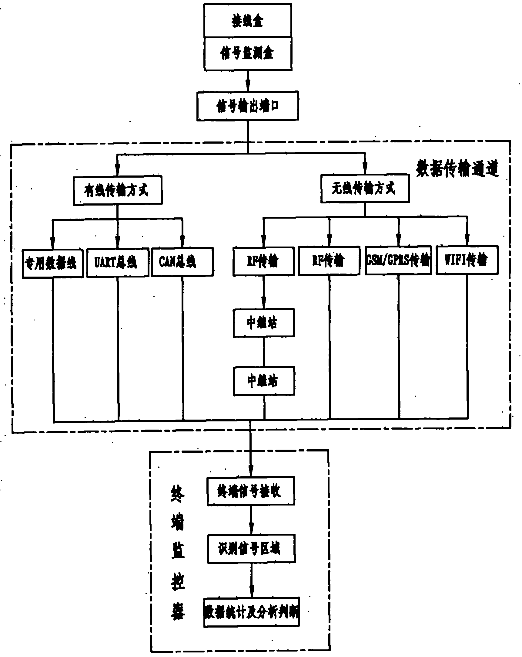
[0015] like figure 1 A working principle block diagram of a monitoring method for a junction box for a photovoltaic module shown, the monitoring method has the following steps: a, an electrical signal collection point is set inside the junction box 1, and voltage signals, current signals, and current signals in the junction box 1 are collected. The temperature signal and the magnetic flux signal pass the collected signal into the signal detection box 2 through the wire; b, the signal detection box 2 processes and calculates the received signal and outputs the obtained data through the signal output port 9; c, the data transmission channel transmits the signal The data output by the output port 9 is transmitted to the terminal monitor; d, the terminal monitor identifies the received data, and confirms the area corresponding to the photovoltaic cell assembly where the junction box 1 is located; e, the terminal monitor performs statistical analysis on the data, Judging the workin...


PUM


Abstract

The invention discloses a monitoring method of a junction box for a photovoltaic module, comprising the following steps of: a. setting an electrical signal acquisition point inside the junction box, acquiring a voltage signal, a current signal, a temperature signal and a magnetic flux signal in the acquisition junction box and transmitting the acquired signals into a signal detection box; b. processing and calculating the received signal by the signal detection box to obtain data and outputting the data through a signal output port; c. transmitting the data output from the signal output port to a terminal monitor by a data transmitting channel; d. identifying the received data and determining the corresponding area of the photovoltaic module, in which the junction box is arranged by the terminal monitor; and e. counting, analyzing and processing the data, judging the work state of the junction box, determining the actual work condition of a photovoltaic battery plate string corresponding to the junction box and positioning to find out the damaged battery plate by the terminal monitor. The invention solves the problems that the actual work condition of a photovoltaic system cannot be effectively monitored and controlled currently and the damaged battery plate cannot be found out by one-step positioning.

Description

technical field [0001] The invention relates to the technical field of photovoltaic systems, in particular to a monitoring method for a junction box for photovoltaic modules that can monitor the real-time working conditions of the photovoltaic system. Background technique [0002] At present, the junction boxes used in photovoltaic systems generally only have a single connection function, which cannot reflect the actual working conditions of the connected photovoltaic modules. When a battery in the battery string in the system fails, the current It passes through the diode in the junction box connected in series and parallel with the battery slice. After the diode continues to work, it will generate heat and lose part of the electric energy. Because the diode works under high temperature for a long time, it is very easy to cause damage and short circuit, thus The power generation of the photovoltaic system is reduced. Therefore, it is necessary to find out the faulty cells a...

Claims


Application Information

Patent Timeline
IPC IPC(8): H02N6/00G01R31/26H02S50/10
CPCY02E10/50
Inventor 吕纪坤
Owner JIANGSU JIUDING SOLAR ENERGY SYST
Why Eureka
Try Eureka