New electric tractor
An electric tractor, a new type of technology, applied in the field of tractors, can solve the problems that it is difficult to meet the design requirements of different forms of electric vehicles, affect the meshing accuracy of the planetary pinion and the sun gear, and it is difficult to ensure the coaxiality of the upper and lower planetary gears, etc., to achieve The effect of compact structure, convenient modification and simple structure
- Summary
- Abstract
- Description
- Claims
- Application Information
AI Technical Summary
Problems solved by technology
Method used
Image
Examples
Embodiment 1
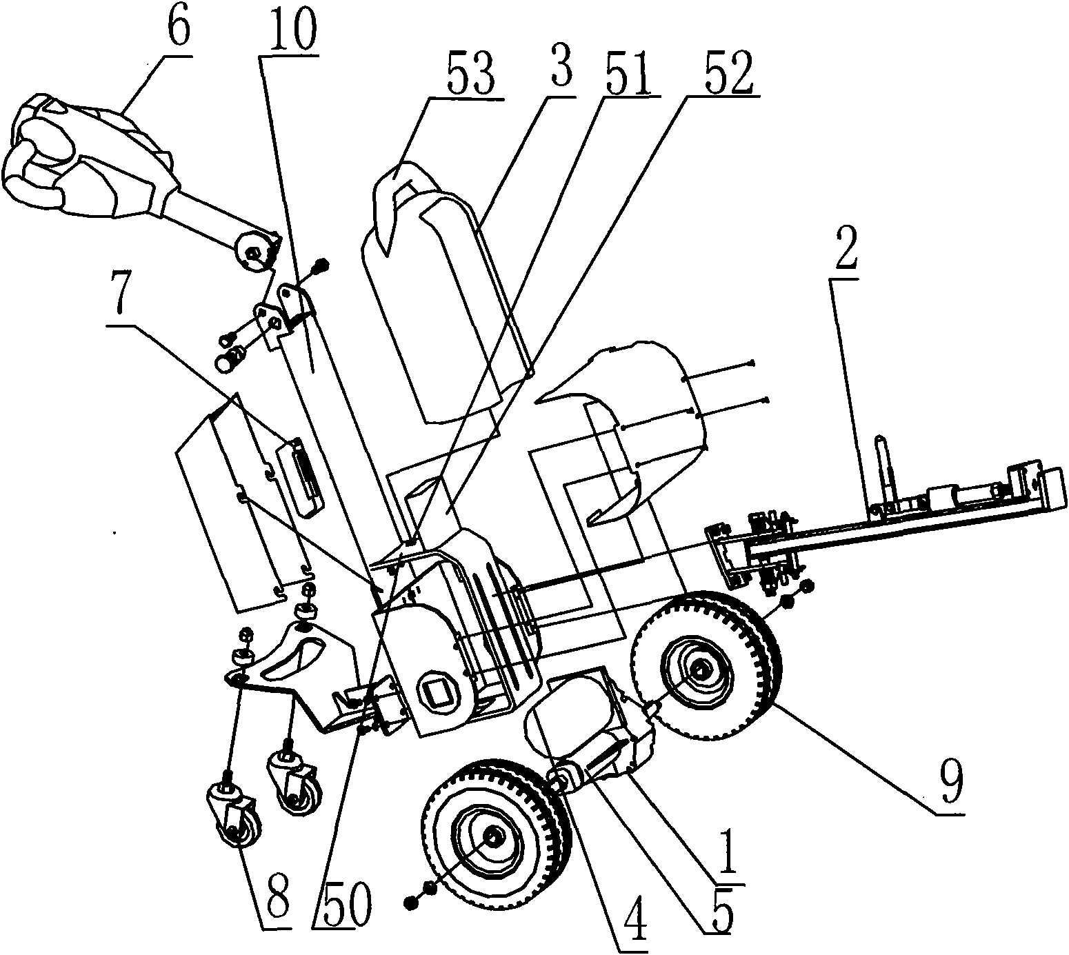
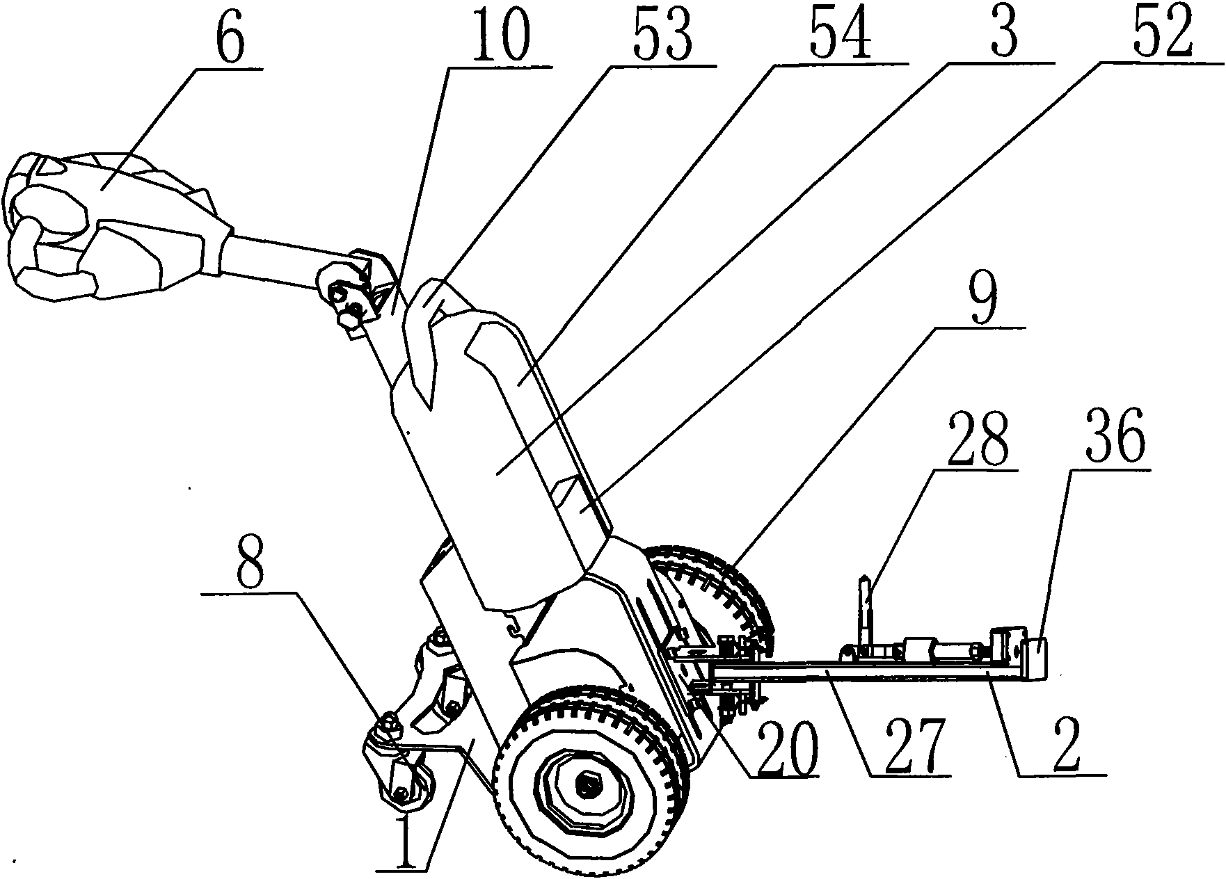
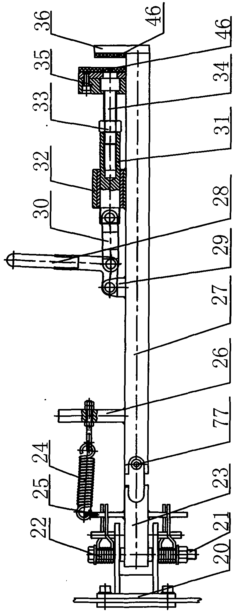
[0037] Such as Figures 1 to 4 As shown, the novel electric tractor of the present invention comprises a frame 1, a traction hook 2, a drive axle 5 driven by a DC motor 4, a speed regulating handle 6, a motor speed controller 7, universal wheels 8 and road wheels 9. The speed regulating handle 6 is fixedly connected with the frame upper pole 10 arranged on the upper part of the frame 1, and the traveling wheels 9 are arranged at the front end of the lower part of the frame 1, and the driving axle 5 driven by the DC motor 4 is connected between the traveling wheels 9 , the DC motor 4 is fixed on the lower part of the frame 1, the DC motor 4 is electrically connected to the power supply equipment, the power supply equipment is placed in the battery pack 3 in the space formed by the battery box 47 and the battery box sealing plate 48, and the drive axle 5 includes Gearbox 11, integral differential 12, left axle shaft 13 and right axle shaft 14, gearbox 11 includes gearbox cover 1...
Embodiment 2
[0046] Such as Figure 5 and 6 As shown, a charger stand for charging a battery pack according to the present invention includes a base 55, a charger 56, a rear cover 57, a main block 58 and a secondary block 59, and a support plate 60 is provided in the middle of the base 55. The upper end surface of the support plate 60 is provided with a quick plug A61 matched with the quick plug 49 of the battery box 47, the front end of the base 55 is fixedly connected with the auxiliary stopper 59 through the fastener 62, and the rear end of the base 55 is connected with the main stopper through the fastener 62. The block 58 is fixedly connected, the main block 58 is fixedly connected with the rear cover 57 through the fastener 62, the charger 56 is placed between the main block 58 and the rear cover 57, and the charger 56 is connected to the external charger power plug 63 electrical connections; the bottom of the main block 58 is provided with a terminal block 64, the charger 56 is ele...
Embodiment 3
[0049] Such as image 3 , Figure 4 , Figure 7 and Figure 8Shown, on the tension spring fixed bar B26, be fixedly connected with the hook tool operation bar 68, be provided with counterweight fixed seat 69 on the frame 1, be fixed with main counterweight 70 on the counterweight fixed seat 69, frame 1 rear end also The electric control box 71 is fixed, the universal wheel 8 is fixed on the lower rear end of the electric control box 71, and the power supply equipment is two batteries 72 arranged up and down, and the two batteries 72 are arranged at the bottom of the electric control box 71, and the bottom of the electric control box 71 Also be provided with secondary counterweight 73, secondary counterweight 73 is placed next to two accumulators 72, and charger 56 is fixed on the top of accumulator 72 above, is provided with motor speed controller 7 in the electrical control box 71 beside charger 56 , Electric control box 71 sides are provided with charger power socket 74, ...
PUM
 Abstract
Description
Claims
Application Information
 - R&D
- Intellectual Property
- Life Sciences
- Materials
- Tech Scout
- Unparalleled Data Quality
- Higher Quality Content
- 60% Fewer Hallucinations
Browse by: Latest US Patents, China's latest patents, Technical Efficacy Thesaurus, Application Domain, Technology Topic, Popular Technical Reports.
© 2025 PatSnap. All rights reserved.Legal|Privacy policy|Modern Slavery Act Transparency Statement|Sitemap|About US| Contact US: help@patsnap.com


