Flywheel type energy-saving turning and throwing machine

An energy-saving, turning and polishing machine technology, which is applied in the fields of organic fertilizer, application, climate change adaptation, etc., can solve the problems of high energy consumption, increased weight, expensive purchase cost, etc., and achieves high drying efficiency, simple structure and easy operation. Effect

Inactive Publication Date: 2011-02-16
王焕坤
View PDF4 Cites 11 Cited by
  • Summary
  • Abstract
  • Description
  • Claims
  • Application Information

AI Technical Summary

Problems solved by technology

However, after the rake bars are arranged side by side, the weight of the rake shaft increases, and a high-power motor is required to drive the rake shaft, and with the increase in the number of rake bars, the resistance of the sludge to the rake shaft increases, thereby limiting the device's impact on the sewage. The scale of sludge treatment, and the purchase cost of the device is expensive, and the energy consumption is high, resulting in increased sludge treatment costs

Method used


Image

  • Flywheel type energy-saving turning and throwing machine
  • Flywheel type energy-saving turning and throwing machine
  • Flywheel type energy-saving turning and throwing machine

Examples


Embodiment 1

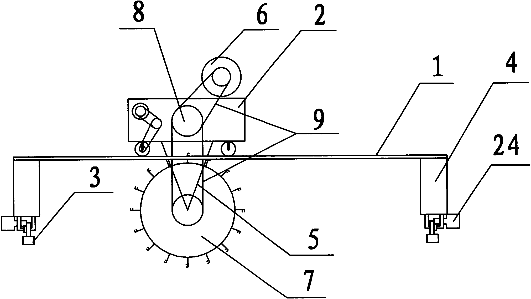
[0030] A wheel-knife energy-saving turning and polishing machine, such as figure 1 As shown, it includes a walking mechanism and a turning and throwing mechanism. The turning and throwing mechanism is fixedly connected with the walking mechanism. The walking mechanism is composed of a horizontal walking mechanism and a longitudinal walking mechanism. 2 is set on the horizontal guide rail 1 and moves back and forth along the horizontal guide rail; the longitudinal traveling mechanism includes the longitudinal guide rail 3 and the longitudinal monorail moving vehicle 4, the longitudinal monorail moving vehicles 4 are connected by the horizontal guide rail 1, and the longitudinal monorail moving vehicle 4 is arranged on the longitudinal The guide rail 3 reciprocates along the longitudinal guide rail 3; the horizontal guide rail 1 is fixed on the longitudinal monorail moving car 4; Fixed connection.

[0031] Described throwing mechanism comprises turning over reduction motor 6, t...

Embodiment 2

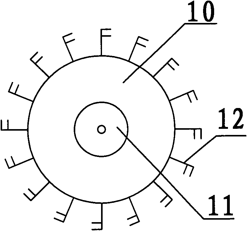
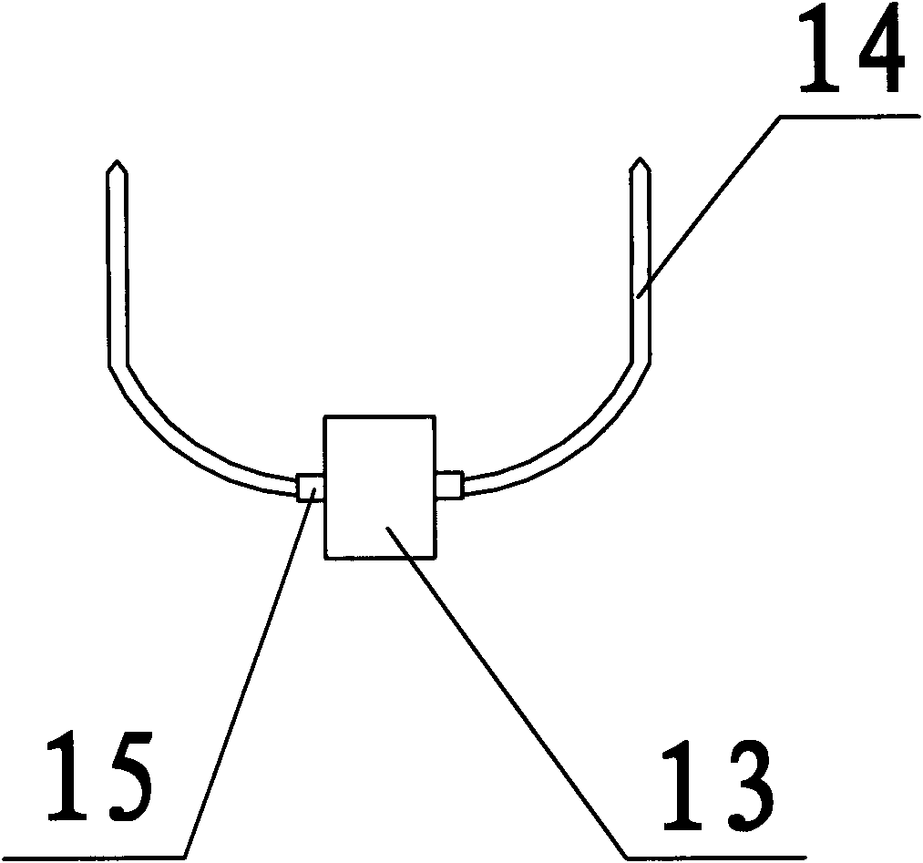
[0037]The wheel cutter type energy-saving turning and throwing machine as described in embodiment 1, the difference is that the diameter of the wheel body 10 of the turning and throwing wheel 7 is 3m; the length of the cutter body 14 is 50cm; 13 The included angle 16 of the projection on the plane where the throwing wheel 7 is located is 120 °; the power of the lateral motion vehicle reduction motor 21 is 2.2kw, the power of the longitudinal motion vehicle reduction motor 24 is 1.5kw, and the power of the turning and throwing reduction motor 6 is 7.5 kw.


PUM


Abstract

The invention relates to a flywheel type energy-saving turning and throwing machine for drying sludge, belonging to the technical field of a drying device. The flywheel type energy-saving turning and throwing machine comprises a walking mechanism and a turning and throwing mechanism, wherein the turning and throwing mechanism is fixedly connected with the turning and throwing mechanism; the walking mechanism comprises a horizontal walking mechanism and a longitudinal walking mechanism, wherein the horizontal walking mechanism comprises a horizontal track and a horizontal double-track sport car, the horizontal double-track sport car is arranged on the horizontal track and reciprocates along the horizontal track; the longitudinal walking mechanism comprises a longitudinal track and longitudinal single-track sport cars, the longitudinal single-track sport cars are connected by the horizontal track, are arranged on the longitudinal track and reciprocate along the longitudinal track; the horizontal track is arranged on the longitudinal single-track sport cars; and the turning and throwing mechanism is arranged under the horizontal double-track sport car and is fixedly connected with the horizontal double-track sport car. The invention overcomes the traditional linear turning and throwing limitation, a processing scale of the flywheel type energy-saving turning and throwing machine is further greater than that of the traditional turning and throwing machine, and the energy consumption and the cost of the energy consumption are lower than that of the traditional turning and throwing machine.

Description

technical field [0001] The invention relates to an energy-saving turning and throwing machine, in particular to a wheel-knife energy-saving turning and throwing machine for sludge drying, which belongs to the technical field of drying equipment. Background technique [0002] Sludge is the solid sedimentation material produced by water and wastewater treatment processes. As a kind of production waste, sludge treatment often requires a lot of manpower and material resources. With the advancement of science and technology, sludge is gradually applied in the field of environmental protection and fertilizer, realizing the transformation of turning waste into treasure. At present, the water content of sludge raw materials is required to be 20% to 30% in the process of using sludge. However, due to the high water content of sludge, the water content of generally collected sludge usually reaches 70% to 80%, and it is difficult to separate mud and water. , so the sludge drying time...

Claims


Application Information

Patent Timeline
Patent Type & Authority Applications(China)
IPC IPC(8): C05F7/00
CPCY02A40/20
Inventor 王焕坤王毅
Owner 王焕坤
Why Eureka
Try Eureka