Self-adaptive light source lighting system and method for high-precision image measuring device

An image measuring instrument and lighting system technology, applied in the field of light source lighting, can solve problems such as large influence, concealment, and false edge detection, and achieve the effect of good repeatability and stability.

Inactive Publication Date: 2012-07-04
DONGHUA UNIV
View PDF0 Cites 0 Cited by
  • Summary
  • Abstract
  • Description
  • Claims
  • Application Information

AI Technical Summary

Problems solved by technology

[0003] At present, there are various structures of lighting sources used for image measurement, mainly multi-angle lighting ring lights, strip lights, coaxial lights, Dome light sources, etc. However, the above types of light source configurations will more or less cause the following problems, Scattering and overexposure hide important information of the image; shadows cause false detection of edges; reduction of signal-to-noise ratio and uneven lighting make it difficult to select thresholds for image processing
[0004] In general image measurement, the selection of illumination intensity is mostly obtained by manual debugging and multiple comparisons, which has the disadvantages of being greatly affected by human factors and low measurement efficiency.

Method used


Image

  • Self-adaptive light source lighting system and method for high-precision image measuring device
  • Self-adaptive light source lighting system and method for high-precision image measuring device
  • Self-adaptive light source lighting system and method for high-precision image measuring device

Examples


Embodiment Construction

[0031] Below in conjunction with specific embodiment, further illustrate the present invention. It should be understood that these examples are only used to illustrate the present invention and are not intended to limit the scope of the present invention. In addition, it should be understood that after reading the content taught by the present invention, those skilled in the art may make various changes or modifications to the present invention, and these equivalent forms also fall within the scope defined by the appended claims of the present application.

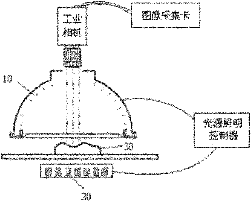
[0032] The first embodiment of the present invention relates to an adaptive light source lighting system for a high-precision image measuring instrument, figure 1 It is the basic configuration and architecture of this embodiment. The light source includes a front light source and a back light source, wherein the front light source is located directly above the workpiece to be measured, and the back light source is located...


PUM


Abstract

The invention relates to a self-adaptive light source lighting system and a self-adaptive light source lighting method for a high-precision image measuring device. The system comprises a light source and a control system, wherein the light source comprises a front light source and a back light source; the control system comprises a microprogrammed control unit (MCU) module, a digital-to-analogue conversion module, a lighting driving module, a serial port communication module and a fuzzy expert system. In the invention, an MCU module is connected with the lighting driving module through the digital-to-analogue conversion module; the serial port communication module performs data exchange with a master personal computer (PC); the PC and the control system form a 'master-slave' lighting control system; the master PC runs a man-machine interface for lighting control and has a built-in fuzzy expert system module and an optimal lighting parameter fuzzy database. When a workpiece is measured, the control system automatically select optimal lighting parameters according to the characteristic parameters of the workpiece to be measured, so the self-adaptive control over the brightness of channel light sources is realized and an image measurement instrument can acquire an optimal image.

Description

technical field [0001] The invention relates to light source illumination in an image measuring system, in particular to an adaptive light source illumination system and method for a high-precision image measuring instrument. Background technique [0002] The light source lighting system is one of the most critical parts of the image measurement system. Its main goal is to project light onto the measured object in a suitable way to highlight the contrast of the measured feature. The light source has a great influence on the image quality. Factors such as the uniformity, geometry, light intensity, light direction, and wavelength of the light source will directly affect the measurement results. It is often the key to the success or failure of the entire system. This requires the light source and lighting scheme The matching of the object should highlight the feature quantity of the object as much as possible, and should produce a clear difference as much as possible between th...

Claims


Application Information

Patent Timeline
Patent Type & Authority Patents(China)
IPC IPC(8): F21S8/00F21V19/00F21V23/00H05B37/02G01B11/00F21Y101/02
Inventor 周虎杨建国朱超陈栋梁
Owner DONGHUA UNIV
Why Eureka
Try Eureka