Heat pump-driven membrane-type liquid dehumidification and energy storage device

A technology driven by energy storage devices and heat pumps, applied in heating methods, household heating, heat recovery systems, etc., can solve problems such as corrosion, damage to indoor facilities, and lack of full heat recovery, and achieve lower condensation temperatures and high energy utilization , the effect of improving efficiency

Inactive Publication Date: 2011-02-16
SOUTH CHINA UNIV OF TECH
View PDF6 Cites 78 Cited by
  • Summary
  • Abstract
  • Description
  • Claims
  • Application Information

AI Technical Summary

Problems solved by technology

The notification number is CN2814209Y Chinese utility model patent discloses a heat pump driven energy storage type solution dehumidification air conditioning system, although it is driven by a heat pump, it does not have full heat recovery and the efficiency is very low
[0005] The common disadvantage of the dehumidification devices disclosed in the above patents is that the treated air is in direct contact with the dehumidification solution, and the air will entrain tiny droplets of the dehumidification solution into the room, causing indoor corrosion and causing damage to indoor facilities.
And there is no full heat recovery, the efficiency is very low

Method used


Image

  • Heat pump-driven membrane-type liquid dehumidification and energy storage device
  • Heat pump-driven membrane-type liquid dehumidification and energy storage device
  • Heat pump-driven membrane-type liquid dehumidification and energy storage device

Examples


Embodiment 1

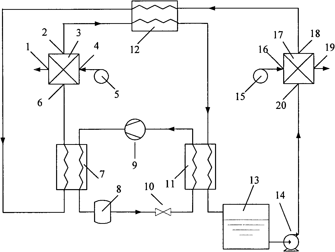
[0047] Such as figure 1 As shown, the heat pump-driven membrane liquid dehumidification device of the present invention includes a dehumidifier 17, a regenerator 3, a condenser 7, an evaporator 11, a compressor 9, an expansion valve 10, a refrigerant accumulator 8, a solution pump 14 and Dehumidification solution storage tank 13. The dehumidifier 17 is connected with the first fan 15 by the air inlet 16, and is also connected with the liquid inlet 6 of the heat exchanger 12, the condenser 7, and the regenerator 3 successively by the liquid outlet 18 of the dehumidifier; The regenerator 3 is connected with the second fan 5 by the air inlet 4, and the liquid outlet 2 of the regenerator is successively connected with the liquid inlet 20 of the heat exchanger 12, the evaporator 11, the dehumidification solution storage tank 13, the solution pump 14, and the dehumidifier 17. connected; the condenser 7, the refrigerant liquid receiver 8, the expansion valve 10, the evaporator 11 a...

Embodiment 2

[0052] The difference between this embodiment and embodiment 1 is:

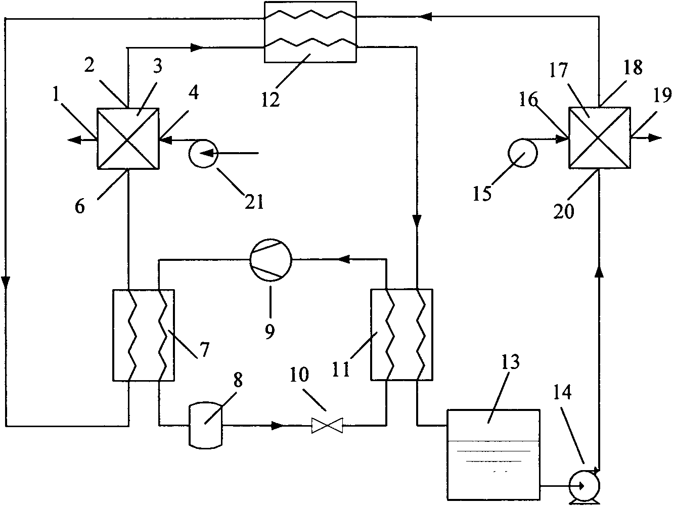
[0053] Such as figure 2 As shown, the indoor exhaust air is used as regeneration air. At this time, the air inlet 4 of the regenerator 3 is connected to the induced draft fan 21 . The regeneration air (indoor exhaust) is sent into the regenerator 3 by the induced draft fan 21, and the wind coming out from the outlet 1 of the regenerator 3 is exhausted as waste gas.

Embodiment 3

[0055] The difference between this embodiment and embodiment 2 is:

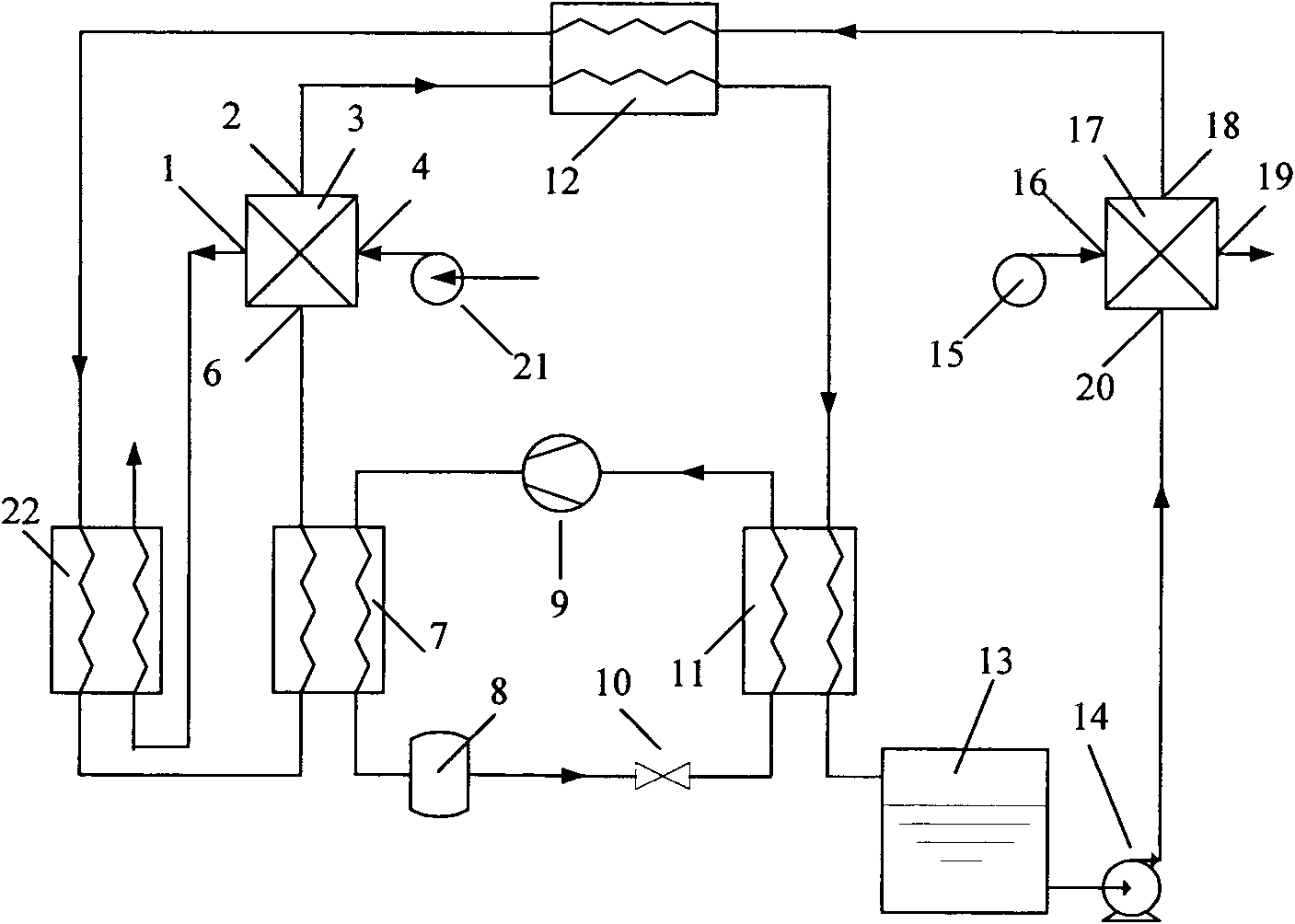
[0056] Such as image 3 The dehumidification and energy storage unit shown recovers waste heat from the regenerator exhaust. The dehumidification solution coming out of the partition wall heat exchanger 12 first passes through the tube-fin heat exchanger 22 (the second heat exchanger), and then enters the heat pump condenser 7 . The wind coming out from the exhaust port 1 of the regenerator 3 passes through the tube-fin heat exchanger 22 (second heat exchanger), and the wind coming out of the tube-fin heat exchanger 22 (second heat exchanger) is used as waste gas and discharged . In the tube-fin heat exchanger 22 , the dehumidification solution goes through the tube side, and the air goes through the fin side, and the exhaust heat of the regenerator is recovered by the tube-fin heat exchanger 22 .


PUM


Abstract

The invention discloses a heat pump-driven membrane-type liquid dehumidification and energy storage device which comprises a dehumidification solution storage tank, a solution pump, a dehumidifier, a first heat exchanger, a fan, a regenerator and a heat pump. The heat pump is a closed circulation loop composed of an evaporator, a compressor, a condenser, a refrigerant reservoir and an expansion valve or a capillary tube which are connected in turn; the dehumidification solution storage tank is connected with the dehumidifier through the solution pump; the dehumidifier is connected with the first heat exchanger and the condenser of the heat pump in turn and then is connected with the liquid inlet of the regenerator; the liquid outlet of the regenerator is connected with the first heat exchanger and the evaporator of the heat pump in turn and then is connected with the dehumidification solution storage tank; the air inlets of the dehumidifier and the regenerator are both connected with the fan; and the dehumidifier and the regenerator are both membrane components capable of isolating the dehumidification solution flowing through the membrane components from the air. The membrane has selective permeability, only allows steam to permeate and can effectively prevent the tiny droplets of the dehumidification solution from being carried in the air; and moreover, the device has the advantage of high utilization rate of energy.

Description

technical field [0001] The invention relates to a dehumidification and energy storage device, in particular to a membrane type liquid dehumidification and energy storage device driven by a heat pump, which can simultaneously realize the treatment of sensible heat and latent heat for the treated air. Background technique [0002] Air humidity has an important impact on human health, so it is necessary to take effective measures to ensure that the air humidity meets the requirements. Studies have shown that the suitable relative humidity for the human body is 40-60%. An environment with too high humidity will increase the discomfort of the human body, and will also cause a large number of certain viruses and bacteria to multiply inside the building. Especially in the southern part of our country, the climate is hot and humid, which often brings sultry and humid feeling to human beings. In order to create a suitable indoor relative humidity environment and protect human health...

Claims


Application Information

Patent Timeline
Patent Type & Authority Applications(China)
IPC IPC(8): F24F1/00B01D53/26F24F3/147F24F3/14
CPCY02B30/52Y02B30/123
Inventor 张立志黄斯珉裴丽霞
Owner SOUTH CHINA UNIV OF TECH
Why Eureka
Try Eureka